Nice looking host Tom, but that name… ![]()
The share for the rev01 is up for the SRK-lite board. Only difference with rev00 is the board outline. Added some friction-fit tabs and pry holes:
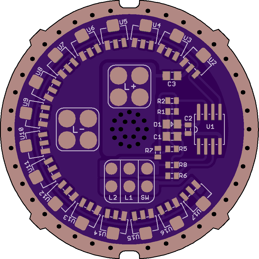
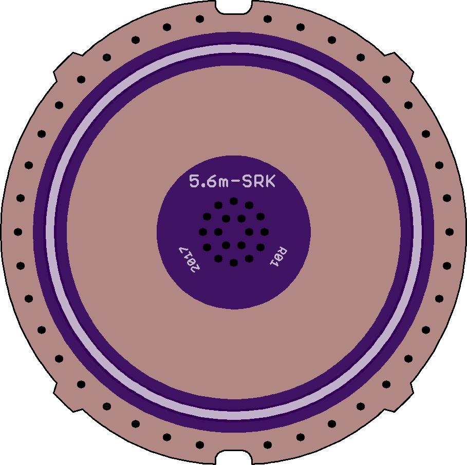
Not sure which version I prefer, will leave both shares up.
Nice looking host Tom, but that name… ![]()
The share for the rev01 is up for the SRK-lite board. Only difference with rev00 is the board outline. Added some friction-fit tabs and pry holes:
Not sure which version I prefer, will leave both shares up.
I do like the tabs - sometimes you do need that extra material for a good press fit. For the pry holes, there could be a better solution. You need a good tool to use them without scratching up the threads (I've done this), then you could break thru the anodizing on those threads which makes intermittent electrical contact when screwing on the battery tube. Many of these cheap SRK's though have poor thread anodizing anyway, so maybe not so much an issue.
Not sure how to do this better - maybe couple enlarged ground thru holes, or maybe couple large holes little further in from the edge so it clears the underlying ledge? Really not sure what the best way is, but should match up with an appropriate tool. I've used a pry tool with a hook or bent end - seems to work best. Hard to avoid some light damage to the PCB. Most people won't be popping these in and out anyways.
Yes, the pry holes were useless on the Ultrafire host that started this. The board was jammed in tight and I think there was some superglue involved as well.
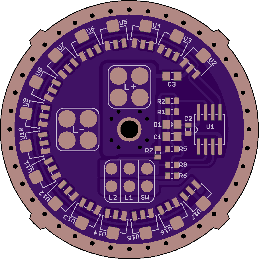
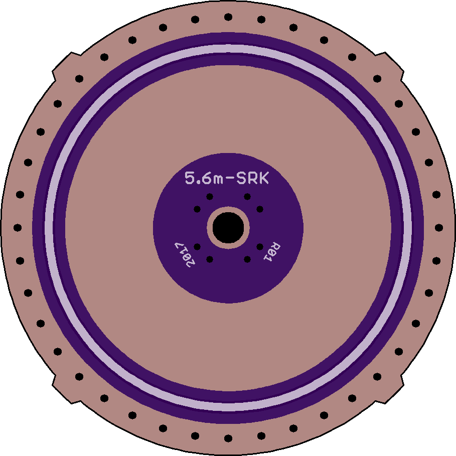
The pry holes on the OSH board above are oval/flat, to be used with a flat 90-deg pick. Or a cheap flat screwdriver with a bent over tip. Round picks would damage the PCB.
A nice option would be a hole, off the ledge as you say, with a small nut glued over it on the component side. The board can then be pulled easily with a bolt screwed in from the back when needed. Would be easy to change the center +vias to one large via for this purpose.
Very very nice features on that board.
Now I’ll be the one to start some borrowing ![]()
I really like the tabs. Less material to remove if not needed, but probably even better contact as it makes for 4 contact points. And: no extra cost because they are put diagonally and do neither increase width nor height.
Has anyone noticed how the tabs and the 7135 match with the alignment of the GND holes? I’m a big advocate of form follows function, but those details really get me.
Pry holes. Real pita when you don’t have them… Although even a present cutout makes it difficult to get the board out in an SRK. There’s simply not enough leverage. But 2 opposed cutouts… and long pointed pliers… and turning instead of levering… I need to test this.
Oh, and routing LED- on the inside of the 7135 instead of underneath them. I had this on my first draft of the BLF SRK V3, but decided against it for better routing of the PWM signal. But the more I look at your board the better I like it, even if PWM goes between 2 legs of the rightmost 7135.
Well done :+1:
Thanks HQ, happy if you find something useful in there! The 7135s are placed on 18 degree radials starting 45 degrees from east. The vias are on 9 degree radials.
There was a small bug on the version with tabs though. The top two and bottom two round segments of the outline had a radius that were a little off. Fixed now in rev01a.
The stock board had 2 round pry holes. I had no luck trying to twist them, but I did not have great pliers in that diameter either.
This version has a center ‘pull-via’, to be used with a glued nut as described above. Off-center would probably work better, but not really space elsewhere for it.
Thanks for the heads up on the L4 Tom, it is a pretty nice host! Got the boards in this week and put one together today.
The rev01 board is a pretty snug fit, no play. Still easy to get out, especially once the spring is on. Went with a 219C for the emitter. Using an SMD tactile meant for the Yezl board, but it works fine.


just ordered DDm17 rev04, can’t wait for them to show up! Haven’t decided which firmware to use and which host, but will probably put this into a ThorFire.
I know I am way late to the party but RE: 7135’s stuck on when run at 2s voltages.
I have had this same issue on several lights. I don’t even use 7135’s on 2S lights anymore, just not worth killing 5 of them to find one that works.
I now just use the FET alone, not a great moon mode but everything else works fine.
I killed like 25 7135’s trying to track down issues before giving up on them.
I can also confirm it is not heat that kills them, I tested them on the bench and the ones that would die, would die instantly. The ones that lived would work fine and get warm but not usually excessively hot. The output would not even step down if there was a good heat path to the host.
Ahh, ok - real good to know. In my 16X XHP50 light, I went with FET+1 in HQ's SRK driver, but the first 7135 died, and the 2nd didn't die but acts flaky - won't turn on. but ramps ok -- weird behavior. I'll drop the 7135 then. Need to generate a FET only ramping table for it. Hhmm using the new Narsil, wonder what temp I should use for thermal stepdown - maybe 80C? Yikes! 
I had some act like that as well, particularly in my 8x xhp50 SRK. I had a lot fail so that they were stuck on a lot current and would not ramp but if I directly shorted the switch pin it would run at full power just fine. Took me forever to figure out that it was in fact a bad 7135 that was causing the stuck on light.
I created an FET only ramp table but not sure how good it is, the moon mode range is not very smooth but not much can be done there. The rest of the ramp is nice though.
Did you use TK’s ramping levels generator? I think that’s what Tom E has been using. Amiright Tom?
Some good data there TA.
Inductive spiking from FET PWM is now even higher on my suspect list. Seems we are OK with 1S voltages, but 2S pushes it over the edge.
Do you recall any detail on when or how fast the 7135s failed? Was it consistently after the FET has been PWMed?
Other big variables are wiring and current. How long were the wires to the LEDs and/or to the power supply? How much current?
Yes, it took some trail and error to get the low modes as smooth as possible but ended up just having to settle for good enough. Even a change from 1 to 2 PWM makes a noticeable difference down there.
That was the strange part, there was not a definitive point that they would fail in my tests. Most would “die” instantly when turned on in modes well below when the FET was activated (aka, they would get stuck on to some extent).
Although if I took it all the way to the FET being activated it was pretty much a guaranty it would kill the majority of the 7135’s.
I think that spiking from the FET is a factor for sure but can’t explain those that died before the FET was activated other then maybe the last batch of 7135’s I got were weaker then prior batches.
The strangest part is when 1 would work perfectly fine for extended periods for no reason I could figure.
Will have to torture a few 7135s.
7135s do not switch that hard, but I suppose its own PWM can also generate fatal voltages under the right circumstances.
Any detail on your setups? Were these drivers in lights with cells, or a test bench with a power supply? When using a power supply it is safer to have a large decoupling capacitor close to the driver. Many power supplies do not handle load switching at the other end of some length of wires well.
I tried it on a few setups both on the bench and in lights.
Most of them died when messing with the L6 TA30 driver in my L6 and my 8x XHP50 SRK with TA46. After those I pretty much gave up on using 7135’s.
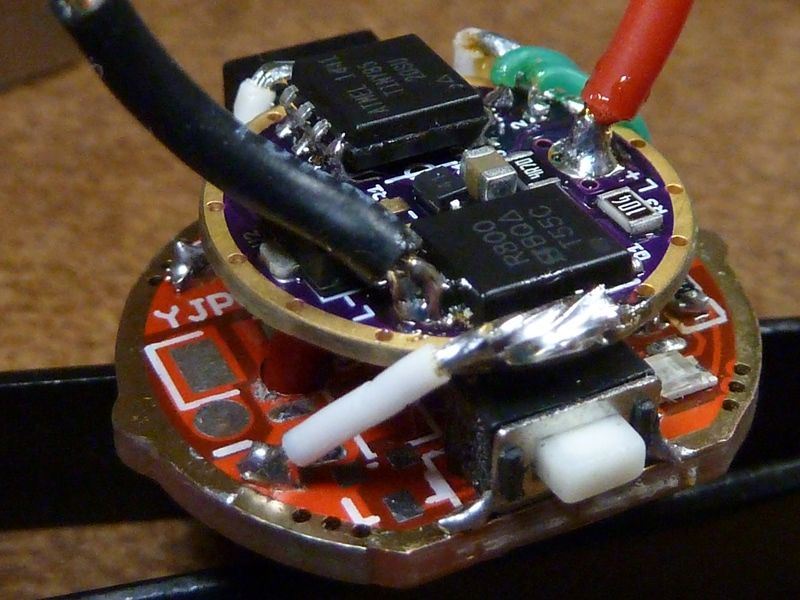
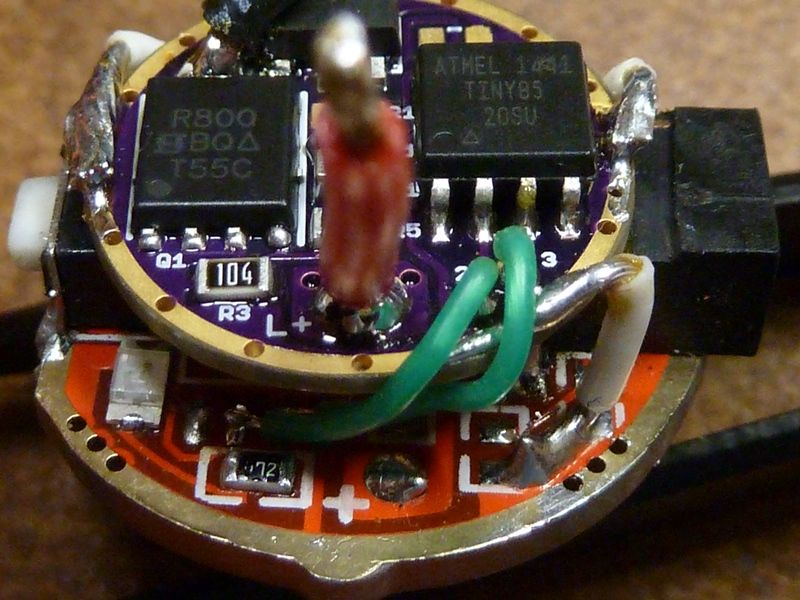
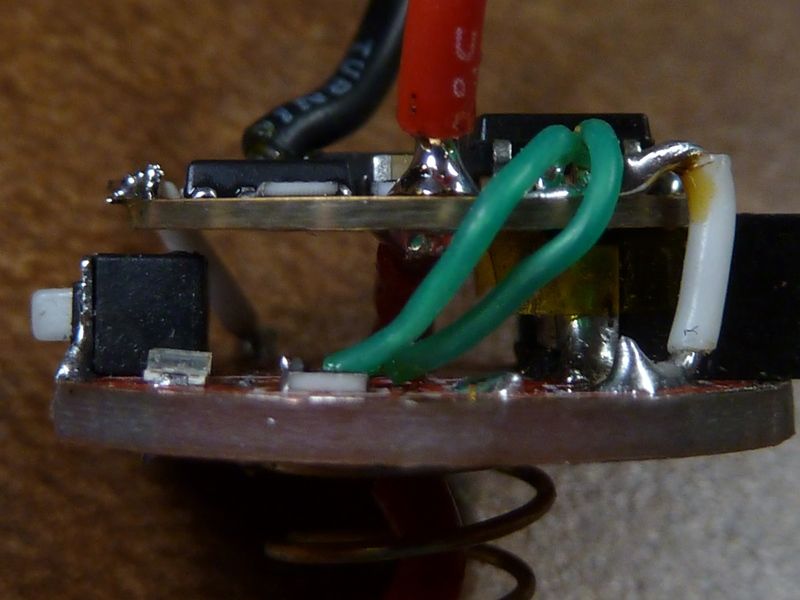
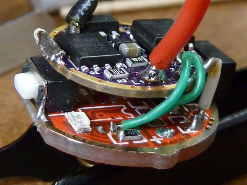
Here's one of DEL's thin 17mm drivers, sandwiched in for a Warsun X60. Clearance is very tight. had to trim down the charger socket. Pictures came out great - these are the best ones I think I've ever taken of drivers. Found a new camera setting that really brings out the detail. Why didn't I discover this sooner?? 

awesome pictures, Tom.
I like how you put the attiny onto the driver, I thought I had to cut & bend the legs, this looks way more elegant.
Yea those are some nice pictures of the driver Tom. I cant wait to see it in person though , I think it will look even better once I have it in hand….lol
I have a pretty new camera that I am still discovering settings on myself. These new ones are just a small computer with a lens anymore it seems , but they can take some great pictures once you figure them out.
I use a some what dated Lumix, so it's a compact but with a nice zoom. The setting that made the difference was exposure. It scales from negative to positive, and found about 2/3 to 1 negative on exposure really enhanced the details and made all the SMD labelings clear and visible, with no special lighting. I'll use room/office lighting (which of course is LED 4 ft lights, fluorescent replacements, in warm tint), plus sometimes use a cheap 14500 zoomie with a Nichia in wide flood mode, high CRI, and double paper towels over the head.