The main interesting feature of the LED Lenser P7.2 is the lighthouse-like optics that puts the full output of the LED into the throw. But another interesting thing is the mechanical driver. Only the Germans would think of a mechanical LED driver. As it comes, it has three resistors, two in the tail switch and one in the head. Of course I bypassed the one in the head, which was always in the circuit. So it switches between two resistance limited modes and direct drive without even an FET in the circuit, in intermittent turbo mode.
I am not sure why they used resistors rather than always on 7135s. Its price in the European and American markets is too high for the cost to be an issue. Probably they figured one resistor is more robust than several ICs, less connections and mechanically and thermally stronger.
Both regulated and unregulated drivers have their pros and cons, as do the various combinations.
Even at work I have been using FET based lights. I do not mind the diminishing output with cell depletion. Extra batteries and charger fill that gap. Even regulated drivers diminish somewhat. As with both, if I need more run time off the same battery I use a lower mode. What I like about the FET drivers is I can get more light output without having to worry if a driver will fit a tube light.
That said, we have the FET+ 1 7135 in the BLF A6 and it works great. Started but never completed was the opposite as mentioned above - 7135's for constant and FET for Max only. If it could be made to just fit a tube light (even if two boards used like some LDCH drivers (??) ) where the stock retaining ring can be used that would be extremely desirable.
I’ll do a 17 mm version sooner or later, but I will be putting the MCU in the center replacing the spring. Moving it out of the center to make way for a battery contact of some sort is too much work to do for a driver I wouldn’t use myself. I spend too much time shuffling components and signal paths as it is.
Would be better if someone could come up with a reliable and still springy solution on top of the MCU instead. If not, I’m personally not the least bit concerned with the wire solution I have in place, but it would be a shame if it’s a show stopper for everyone else.
Has there been any run-time/efficiency tests done comparing (Nanjg based) 7135 & FET drivers?
Ie;
A 7135*8 driver @ 'x' pwm, starting at ~400 lumens, will hold the ~400 until battery drops below regulation, then will drop gradually until LVP kicks in.
Given the same LED & cell & LVP setting, a FET driver @ 'y' PWM, starting at ~400 lumens, will gradually fade with voltage drop, untill the LVP kicks in.
Which will last the longest before LVP, & how much difference between the two?
If the LED output were exactly proportional to the current, then the FET would run longer before LVP because it drops below 400 lumens sooner. That will usually be the deciding effect but it depends on the details.
If the LED is small, so 400 lumens is close to its maximum light output, then the FET driver will need to push much more average current through it to get the 400 lumens than the 7135 driver will. So the 7135 driver will run longer.
In any real case, the 7135 driver will get more total light, integrated over time, than the FET driver will.
Last week I modded my DQG 18650 Tiny III with a FET driver from Mountain Electronics. It was one of the newer drivers that contained a FET for high modes and a single 7135 for low modes.
Unfortunately, this setup proved less than optimum in this light. The Tiny III is a very small light…. Something like 36g and 89mm long. There’s very little aluminum available for heatsinking. Sticking a FET driver inside running on a Samsung 25R and powering triple XPG2 produced awe inspiring output. But the head got too hot to touch in less than 15 seconds. Even at the second highest setting the light was too hot to touch in less than 30 seconds.
And this is an EDC light! My ring around the switch made accidental pocket activation very unlikely. But the idea of this thing turning on at max in the pocket was kinda scary.
At one point I tried the light with a piece of painted aluminum wrapped around the head. This allowed me to hold it longer because the paint and superglue finish acted as insulation… but it didn’t keep the driver and light cool. This test actually broke the driver! The two low modes ceased to work, while the 3 higher modes worked fine. I think the 7135 burned up.
Trying a lower resistance ICR cell didn’t help… it still got too hot too fast.
When I installed a replacement driver, I decided for this particular light, a FET driver didn’t make sense. Instead I used a Nanjg 105c with 4 extra 7135 chips. Instead of whatever it was pulling before (probably 9+ amps), now it only pulled 4.5 amps. The light still gets quite hot, but as long as it is held in the hand, it no longer gets burning hot. Yes I lost output, but now the light is much more practical and much less dangerous and output is still good. I figure output with three XPG2 is maybe 1100-1300 lumens.
Another upside, is the Nanjg105c I used has Dr Jones Mokkadrv, one of my favorite UIs.
This was another reason I tend to be more in favor of regulation. I always thought of DD as being on cheap lights while the more expensive ones are regulated. Basically like taking a step back, but the more I learn I’m seeing there is more to it. Vf for example, I knew nothing about this, then I learned about it, and about voltage drop. I used to hate having cheap store bought lights that got dim when the alkaline cells still had half their juice left. Now I have the same problem with my xml2 lights that cant work under 3.3v. There’s still juice in the cells, but only enough for low or a emitter with a lower Vf. So in a way its not too Different from DD, just a fast dimming instead of a gradual one. When I bought my first regulated light I thought it would stay at the exact same brightness from turn on with fresh cells until the cell was totally empty, lol not that simple.
I did not know that there wasn’t as much voltage drop with FETs. I thought the voltage drop was more a function of li-ion cells as opposed to alkalines, or because of the LED itself. I figured both FET and 7135s had the same voltage drop, but that was a total assumption on my part. Learning more everyday, thanks guys!!
Here’s one more thing that’s got me confused and is a reason I don’t usually go for FET drivers. Being a newbie to all of this, I don’t understand how you can run an LED with 1*18650 and DD. For example, the xml2 data sheet from Cree has the max current rating at 3A. I see people driving a xml2 with a Samsung 25r, lg he2, efest purple etc. Those imr or inr cells can put out much more than 3A, so how is this not making the LED go poof? The 25r can push 20A continuous. That’s 7x the manufacturer specs!? Am I missing something here? I could see the manufacturer under rating their product by a certain amount, and I can see someone over driving the LED for max output, but only by a certain percentage. I would think even an icr li ion cell would be too much at a 2C discharge rate. With 3400mAh cells that’s more than double what the manufacture says, let alone 7x. Even putting the LED on copper and having a step down from turbo, it seems like way too much and it would fry immediately.
Vf.
It takes more voltage than a single cell has to push higher amps.
Just because Cree rates their leds for 3 amps doesn’t mean they can’t take more than that … especially with a big heatsink attached.
Sure it might reduce the lifespan of the led a bit. But does it really matter if the led only lasts 30,000 hours instead of 50,000?
Two effects:
1) The voltage of batteries go down when they produce more current. The Samsung25R can produce that 25A current, but at just 3.2V, and this voltage goes further down during drainage of the battery. I use this graph from HKJ when predicting what current a certain led/battery combination will draw (this one is from the Samsung25R):
/Samsung%20INR18650-25R%202500mAh%20(Cyan)-CapacityTime.png)
2) when the leds are mounted on a so-called direct-thermal-path ledboard (usually Sinkpad or Noctigon) the leds can handle way more current than spec'ed, the XM-L2 up to 7 or 8A. The voltage increases when the current goes up.
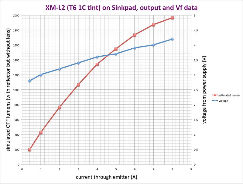
So with increasing current, the battery voltage goes down and the led voltage goes up. At a certain current those voltages 'meet' and that is the current that your led will get.
In a flashlight there will also be several resistances between battery and led (springs, switch, wires, driver). These resistances cause the voltage that reach the led to be a bit lower than what comes straight out of the battery.
I hope this helps :-)
Thanks for the info guys, that really helped clear some things up.
Here’s a funny/ironic story. My latest light was the Eagletac d25lc2 tactical. I’m a big fan of ETs beams and tints, so I went ahead and bought this one. It quickly became my favorite. I really like the turbo setting for the first 200 sec, then it steps down 20%. This weekend while spending time researching FET drivers for this thread, I learned that many lights now go into DD for turbo. I was unaware of that. It appears several of my lights are like this. I guess I like FET more than I thought.
Thanks again for helping with my confusion.
Decided to give a go at a combined 7135 and FET driver. By having the MCU instead of the spring allows me to fit a SO-08 FET together with 10 x 7135 on a 17mm board with all the other stuff (off time cap, voltage divider and zener). Caps are 0603 size and voltage divider resistors are 0402.
I didn’t budge on the MCU in the middle but what I did do was add a via on the opposite side of the MCU for the stiff copper + wire. With this I just create a bridge over the MCU without the wire resting on it. I can then monitor how much pressure is being applied by the cell by checking how much the bridge gives way, and if it doesn’t it’s the vias that take the load, not the MCU.
It’s 17mm but as I make my drivers to fit specific lights I just change the board outline to what ever diameter I want (17.7 for S3 with integrated shelf, 17.5 for S2 and S2+).


What is the FET of choice today? Been doing some searching and I know wight has used the PSMN3R0-30YLD, and djozz got some cheaper FETs but appear to be sold out by that seller.
Sweet! Awesome work Mike C! How many channels are in use on this board? Is there a 1x 7135 channel? Or just one channel for the FET and one for the 10x 7135?
Three 7135 channels for 1, 3 and 6 x 7135s, groups are labeled 0 1 and 2 on the board. I put the FET on PB5 and gave it a via so it easily can be soldered to the chain of 3 or 6 x 7135s for testing before enabling the reset pin.
Wow! Nice work!
Mike C, the SIR800DP-T1-GE3 is the best performing SO-08 FET out there ![]()
It is expensive though ![]()
If it is tight with so much components & a SO-08 FET, maybe try to use a smaller FET like the PSMN2R4-30MLD in a SOT-1210 size, that wight & Richard have used in smaller 10mm-12mm drivers.
Thanks for the tips. I think I’ll go with the PSMN3R0-30YLD for the first trial though. It is a tight fit and as you can see the edge of the tab on the FET footprint slightly overlaps the 7135s under, but I’ve allowed this as it looks like I can cut off a piece of the tab on the PSMN3R0-30YLD as I do with 7135s on these tight boards.
If you used a attiny13-mmu + the smaller FET you could probably fit both of those on top and fit a spring on the bottom, for possible users that doesn’t like the idea of having the bat+ be on top of the attiny ![]()
That’s what the additional via is for, to support the wire over the MCU like a bridge. It won’t touch the MCU. Also, the 85 footprint I use is smaller than the 13A footprint because I made a custom 85 footprint for bent legs, so no gain there unless you make a 13A footprint with bent legs… which I won’t do, I’m done with that little thing.