A C12 huh? I had never gone for the C8, but now that I have, I like it. The SupFire F9 is similar, slightly deeper reflector, but also a nice beam profile.
I find myself drawn to the floody field of silky goodness produced by MT-G2 lights though. Can’t help it!
An LED only radiates forward light so it only requires a forward reflector. Having all the correct angle of incidence’s on it is all that’s needed. If it gave older light sources the best etendue possible using those same angles, it would work just as well with LEDs.
Anyway, here's an update. I made and polished a 2nd reflector. It looks OK. There are still ridges that I wasn't able to polish out in the 5 or 6 minutes that I went at it. I may be able to get them out with more work, but I'm not happy with it. I'm going to machine a 2nd bit. The biggest problem that I had with the first one and second one for that matter was that there has to be a relief angle behind the cutting edge and it's difficult to machine that angle along a surface that has changing dimensions so I machined it as close as I could, then hand filed it. Honing took care of most of the ridges but not all of them. Also, my little dremel can't get all the way down in to the bottom.
Suggestions for which equation to use for making the next bit?
Here are a couple of pics and a video of me turning the first bit on the lathe.
Since you guys are talking about parabolic reflectors I thought I might re-post this video I made. I passed an opaque object in front of an HD2010. First try to guess what happens before you watch the video. Then as you watch, notice what is REALLY happening.
BTW, I think that it is important to remember that, as someone pointed out, a parabola is only perfect in the math. In reality anything we construct is at best, a close approximation. Also for infinite throw the light would need to be a point source. Mathematically speaking, that is an infinitesimally small emitter. In real life most of the surface of any finite sized LED is always slightly out of focus, no matter where it is placed. That is why the hot spot obeys the inverse square law.
In the video, notice the effects of the object on the spill, flood and throw of the light.
That’s a lot of work! I can see myself with a lathe, and still hitting the part with a file by hand. lol
I love watching the shine come up when stepping to finer and finer papers, and then seeing what the polish does. That mirror finish makes it all worthwhile!
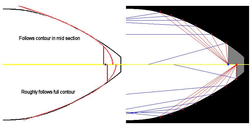
I don’t have many lights to compare but the my XinTD V3 produces a well-defined hotspot and no rings at all. It’s about as good as it can be in my opinion. I’d use that profile and make a female cut-out (scaled down if you like) on thin cardboard. After machining the profile using the formula, finish by filing/sanding using the cardboard cut-out as a guide to check your progress and make adjustments. If you don’t have a known good reflector, your best bet is to use the formula for the cut-out.
I can’t say whether the formula is perfect or just close but measuring the angles in the image posted earlier, it seems right. Scaling it up to a much larger size would allow more accurate measurements and adjustment if necessary but I think it’s more than good enough for a small reflector that isn’t going to throw very far anyway.
Here’s how far off your profile is. If it was do to the camera angle, the angle at the end should be at least 45 degrees but it’s less. It’s off by at least 5 degrees for a good portion of the total reflector. That would create a “spot” 10 degrees off all around that section’s circumference. Hopefully, together with the angles that are correct, the beam pattern will just have a big spot blending nicely into the flood and not be dark in the middle. Unfortunately, without having some portion of the reflector match a parabola precisely and focused on infinity, there’s no guarantee that the center will be brighter than the corona at various distances or at all.
It’s my understanding that the area immediately surrounding the die is responsible for the spill. The area further up towards the bezel is what makes the hot spot. This has been demonstrated by placing a circular item in the middle of the lens and observing the beam. When the middle of the lens, the area directly over the emitter, is blocked, there’s pretty much nothing but a hot spot. When the outer is blocked with something like a washer (think donut) there is nothing but spill. Try it.
Edit: If it’s true that the emitter has an emissive angle of 125º, then only about half of the area being pointed out is actually an issue anyway. And from what it looks like, this area will affect the spill more than the hot spot. Guess we can only mount it over an emitter and find out!
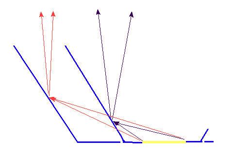
Also remember that the non-reflected rays will cause spill. There is a significant angle from the emitter that will never see the reflector so it is not re-focused (columnated). Pretty easy to calculate if this is the effect you are seeing in the spill pattern by calculating the angle of the source to the end-edge of the reflector. That is the spill you can expect. This is a significant amount of light.
I believe the spill comes from the light source at angles that never hit the reflector. Throw or Spill.....how about BOTH?!! | Candle Power Flashlight Forum!!
The wider the reflector for a given length the more spill. The deeper the reflector for a given diameter the more throw or something like that. I remember seeing this discussion some where before I think.
This thread is turning into exactly why I said this stuff just “fly’s right over my head”. :bigsmile:
A 125* veiwing angle means the brightness beyond 125* has dropped to 50% of the direct forward 100% brightness. It drops off gradually so it might be 60% or less at 90* and up to 50% at 170*. There’s no fine dividing point where brightness suddenly drops off at the specified veiwing angle.
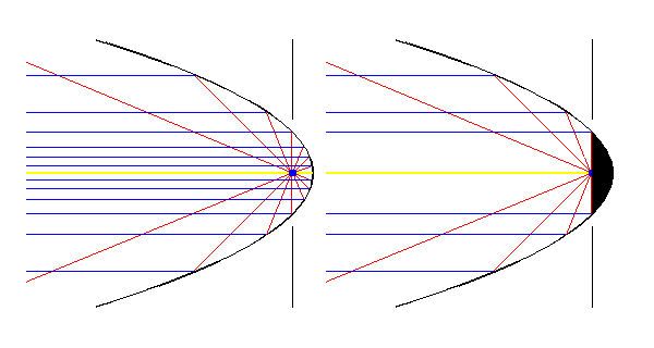
I could say my XinTD gives the LED a veiwing angle of about 60* (basically spill). Ignoring losses, the remaining 120* is reflected to 0* (measured at LED center). There’s probably not too many flashlights that purposely try to achieve more than 0*. There’s a point of diminishing returns when attempting to reflect more spill by making the reflector longer. The length grows exponentially per degree gained.
I didn’t understand what you were asking but I think it was this. The blue dot shows a compromise of about where the LED should be. The red dot is back too far and would probably just flood, maybe even darker in center. I’d expect the patterns to change more with distance.
How does an led not being a point source affect this graffic? Also , the output isn’t consistent over the entire 125 ^ arc so maybe placement should maximize parallel rays in the arc area where output is highest. This is an interesting thread to read.
I’ve been trying to find a way to express that “reverse engineering” concept.
I’m new at this, so I keep thinking “A Parabola is the optimal reflector for a 3D point source like an Incan or HID.” We don’t have that 3D point source; ours is 2D. The TIR Optics attempt to correct that by putting a wee “recoil” reflector where the Focal Point should be…
My prediction is, this “LED-Optimal” reflector will end up being “too deep”…
From what I have seen with my eyes, from mods over the years, with a given depth, the wider the reflector, the smaller the spot and with a given width, the deeper the reflector, the larger the spill ring. That's why I see large OD short reflectors give the tightest spot and small OD deep reflectors give the most spill. All I know is what I see, but not the science behind it. For instance, this reflector produces a smaller spot and smaller spill ring than this reflector, with the same XM-L led.
At some point, a parabola curves down to a 45* angle. Using the center point of any light source as the starting point, the light must hit that 45* point at a 45* (angle of incidence) and bounce off at 45**. This is how deep the light source must be to get an 0** direction. If you have light source that has a circular filament, everything changes and a parabola probably wouldn’t be the best shape to use.
It’s not 3D vs 2D, it’s 360* vs 180*. An LED doesn’t have any back light so we just cut off that unused part of parabola. That’s the only difference.