Looks like a perfect bullet. A very large perfect bullet! ![]()
Yes, much nicer! ![]()
Does anyone remember creating an image of a solar eclipse thru a pin hole? This also works great to see what pattern each part of a reflector creates.
Put a pin hole in the middle of a card or piece of paper (smaller is better) and hold it over the lens. Centered shows an inverted image of the emitter directly. This is from the spill and it’s pattern won’t change no matter where you move the pin hole. Now, move it slightly until it’s just over the deep small section of the reflector and another very distorted yellow image appears. This area produces the corona and it’s a reflection of the emitter edgewise (side view) so each point at that circumference creates a crescent shape. Collectively, they make a big fuzzy spot with artifacts. Move it closer towards the edge and that distorted image becomes clear enough to see the tiny wires. This part reflects the emitter more head on so it creates a smaller well-defined spot.
We flashoholics are so easily entertained. ![]()
Let’s look at the angles formed by a small parabolic reflector. (A larger C8-sized reflector will produce angles roughly half the size.) Not all my numbers are exact but close enough to get the idea.
Here you can see that the beam angle gets better where the reflector surface is farther from the source.
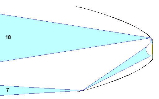
Further back where the only the emitter’s edge is being reflected, the beam angle looks even better. (The 2* is a guess since I can’t measure the edge of the phosphor.) But lets rotate that reflector 90* so that point is at the red dot and take another look …
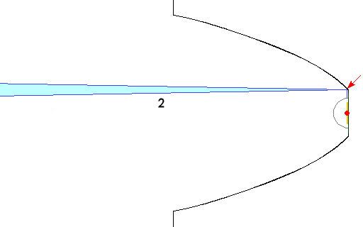
Now it shows a beam angle of up to 80*. I’m not sure how much but I think the beam pattern at that point curves with the circumference forming a crescent so it’s not as bad as it looks but still far worse than what any points more forward would create.

Edgewise, the emitter is a long line of points so while it creates a narrow angle in one axis, it has a wide angle in the other. Also, the side of the emitter is in close proximity to the reflector which gives a wide angle.


It seems to me from this that more is gained from having an accurate shape at the outer half of the reflector where the luminous intensity is higher. Since keeping the overall size of the reflector as large as possible will make the led more nearly imitate a point source then deepening the reflector to capture and focus more of the spill has a trade off against the relative diameter of a reflector. A big diameter relative to length loses more spill but focuses the light captured better than a narrow parabolic shape which has less spill but poor focus. Question: is there an optimum proportion of die size to parabolic shape for a given available length or depth? This was hard to visualize as well as describe so pardon me if it doesn’t make any sense.
I’m very glad you guys can fathom all this, as it looks much more complicated than y’all are showing.
It’s one thing to take an imaginary single point from the surface plane of the die and extrapolate a theoretical angle of emission. It’s a whole nutha thing to imagine how many single points are in that square, extrapolate and merge them and then correlate them to a circular parabolic 3D reflector. (especially since a parabola is a single plane concept)
Me? I’d be making reflectors til I found one that did what I wanted, no mathematics required. ![]()
Wanna make it even more complicated? What do you want the beam profile to be? Which emitter? Got it just perfect? Now what will you want tomorrow? The day after? To work on the leaky oil pan? Find the lost pup in the back 40? Read a book in the hospital while the wife recovers from surgery? Tell spooky ghost stories with the light under your chin? How many different needs are there, while we search for the “perfect parabola”? Do all those needs have the same beam profile? If so, do I have to get rid of my other 32 lights? ![]()
Perhaps this is why I’m enjoying the MT-G2 so much. Just freakin flood EVERYTHING with awesome light and be done with it already! lol Did you see the beamshots in MRsDNF/O-L’s Mag? That’s what I’m talking about, wall to wall floor to ceiling hither to yonder hello who needs the sun one click flashing. Bingo! ![]()
Amen to that!!
You are inspirational, though.
I had the idea of mashing the Parabola drawing over the Spatial Distribution drawing to try to visualize some “optimal” arrangement. I mean, the little lines showing how beams reflect are nice (not-to-mention drop-dead critical), but still somewhat theoretical, as there seem to be “more lines” (higher intensity) in some directions than others, vs. the “ball-o-light” from a burning wire or plasma…
So while I put ice on this headache, what about the curve of the Spatial Distribution graph?
What would happen if that curve were carved into the reflector? Obviously the LED would be at what is the “peak” of the graph, but would that curve give us a decent beam? Or is there some mathematical “compliment” to that curve?
I can only ask, and hope for sanity and sagacity from you guys…
It’s really not that complicated. I use a the parabola as a baseline because it’s a known shape with known results. An ellipse might give the desired results but there’s too many variables and each will produce different results.
The base of a parabolic reflector is 45* regardless of size if you want to focus on infinity.
A large emitter or small reflector creates a large spot. A small emitter or large reflector creates a small spot.

Isn’t the spatial distribution curve a plot of the intensity of the lumens as radiated from the die? So of course it’s brighter straight out of the die with lower lumenosity away from the center. Can this be directly plotted to the parabolic curve of the reflector? Can all this actually be directly graphed to the growing intensity of the pain behind my eyballs? You’re not alone Dim….
Edit: FWIW, Alt 167 creates the degree symbol
Edit II: Buck, if all this is super critical and if lightme’s diagrams are correct, here’s your image overlayed with his diagram. You’re REALLY close to computerized perfection! ![]()

I wonder if you have something reversed. Here’ the original profile mirrored and tilted. Looks like a near perfect match to a parabola. This why you should use a parabola-shaped cardboard female cut-out for finishing. If you don’t want a well-defined spot, it still might work fine as long as the wide end follows a parabola.

You guys amaze me with all of this analysis.
Update: I have about 80% of the mill work done on the latest bit. I should have it done today or tonight with results (if I don't turn a hand wheel the wrong way and ruin it.) My mill skills need much improvement.
Buck, we’re eagerly anticipating your success! Sitting here on the edge of our seats, we have to discuss Something! ![]()
This is neat. Keep it up!
Hopefully, this will help with that.
It’s temporary, of course, but easy enough to make or remake and deploy as needed. Just cut on the lines…
Hopefully, there’s some place on or near your feed wheel which can hold this…
Print this at 100% size, each box should be ~1” high inside the lines:
Obviously I don’t know which box matches your wheel…

Dim, is that from the top of the wheel or the bottom?
wiseguy! ![]()
I'm willing to call this last effort a partial success. But I am still not happy with it. Here are some pics.
After the cutting edges have been machined. It's held in a collar that I made so that I could hold it in the vise.


Finished bit prior to hardening


First Cut unpolished and polished


I'm disappointed with how much force that it takes to cut and that it seems to wander in the hole. You probably notice that the hole at the bottom looks too big. It is. I made the bit too big. On the plus side, it gives a reasonable finish. The second, polished picture is after less than a minute of polishing with the Dremel and some jewelers rouge. I only did it for a minute because my Dremel died. Grr.
I am still pleased on the whole. I once again learned from this. My next attempt will look more like a spade bit with a pilot on the end to guide it down the previously drilled hole. The greatest problem that I have is machining the relief angle on the cutting edge. I may have to do a spread sheet for the mill to help me out. Doing it by eye isn't working out too well.
I love what you are doing Bucket. Just a thought. What if the cutter had a spigot on it and a pilot hole for the spigot in the material being bored. It may stop a bit of wondering. You could possible add a little bit more relief on your existing cutter with your new dremel?
I’ve found that my dremel collects metal dust under the variable speed switch and that burns the two strips and leaves a residue behind when you move the switch side to side over the two metal strips that give variable speed, this is what has usually stopped mine in the past. If you get the body apart you can lift out and unplug the switch and just scrape those two strips and the prongs that touch them with some fine sand paper so you have bare metal again, and that might fix your breakdown, Good luck hope it helps.
Bucket, that looks pretty good to me. I can definitely see how the cutting relief would be hard to cut with the curvature of the cutting edge. The cutter you are making reminds me of a countersink bit. This is about the best picture I could find that illustrates the cutting relief behind the cutting edge. http://www.ebay.co.uk/itm/3PC-COUNTERSINK-DRILL-BIT-SET-CARBON-STEEL-COUNTER-SINK-BITS-12-16-19mm-DIY-/400619839436?pt=UK_Home_Garden_PowerTools_SM&hash=item5d46cd9fcc
I know you probably already know what it needs, the problem is just getting it there. It will probably always take some pressure to push into the cut, the whole length of the cutting edge is taking material with ever rotation. It might improve with more cutting relief but I would say its always going to take a bit of pressure to remove material.
I might be interested in buying one of these reflector cutters when you get it perfected. Looks good. ![]()
Have you tried any of the mothers aluminum polish yet?