I think it matters how much light is hitting the meter sensor at a given distance, no matter where it comes from.
http://flashlightreviews.com/features/lux.htm
Thank Moderator007. That's a nice layman's language resource. I bookmarked the site.
So it sounds like we would theoretically get 900kcd as long as the hot spots overlap each other. Triple the photons would be crammed into the same space.
I was playing with a camera last night. I think will be able to retake some pictures at more resemble what I actually see. I'm still getting pictures had either exaggerate or understate the light. The pictures above exaggerate the hot spot's intensity.
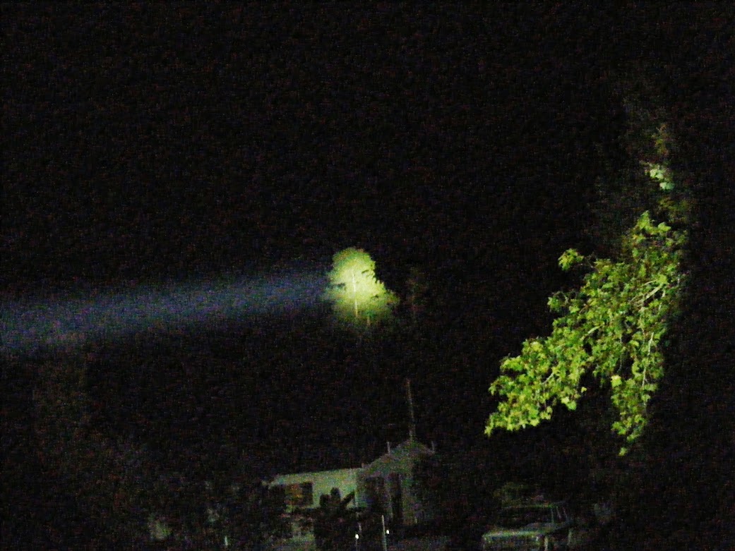
I don't like the above beamshots. So I played with the camera setting and picked a new location. I'm still not quite satisfied. The shots seems a bit darker than reality in all the shots below. Especially, in the distance. Also, the tints in the picture seems a tad greener and tad less warm. I don't know how far it is to that first visible crest in my driveway. I will try to measure at some point. I tried to aim just over the crest with some of the hotspot hitting the crest.
Supfire M6 on high (Unmodded)

Shadow JM26 with XM-L U2 2C on high (Modded) - Sorry beam is pointed low on this shot

DST with XM-L2 U2 1A on high (7 amps to emitter. About 35 watts consumed)

DST with dedomed MT-G2 (about 6 amps DD. About 50 watts consumed)

The DST is not the ideal candidate for the MT-G2 on account of the narrow spill. I think the Illumination Machines LUM5-90 reflector is the best because it has wider than SRK spill, better flood, and very good throw. It is the best reflector I have used with the MT-G2. I am building a custom light with it now. The emitter will retain the dome as it works best with the dome in that reflector.
EDIT: Sorry to bump my own thread with an edit, but I just realized I had miscalculated wattage consumed on the MT-G2. Calculation is based on resting voltage of cells times current measured at tail. So, actual wattage would be lower due to voltage sag. The MT-G2 will sag more as 6ish amps are being pulled from each of the 2 cells, whereas, the xml2 only pulls 2.8ish amps per cell.
Nice shots. They show the difference between the lights well. Have you a picture or point me to a picture of this. Illumination Machines SST-90 reflector. Thanks.
Magnificent results. 
Go point it across the highway and strip the paint off passing cars. 
MRsDNF wrote:
Nice shots. They show the difference between the lights well. Have you a picture or point me to a picture of this. Illumination Machines SST-90 reflector. Thanks.
You are so cool. Your shots are like art work, but you still try to encourage others at all stages. You the Man!
Here is a product link. It is called the LUM5-90 (couldn't remember name when I typed the above).
http://www.illuminationmachines.com/products.php?id=9&catId=1
It only gave me 54kcd when I tested it with dedomed MT-G2. I think it's possible that it may actually throw better with the dome. It's a big reflector. One thing for sure, the beam with a dedomed MT-G2 was not nearly as appealing as with a domed emitter.
When I used it doomed, it was the most beautiful beam I had ever seen. It was like SRK on steroids and with throw to boot. I can't put my finger on it, but everything seemed more 3 dimensional and solid. I could even spot the spiderwebs that I generally walk into. Maybe the facets send the light out to the same spots from different angles. I don't know, but it was kind of magical to me. I tend to get over excited about these kind of things at times. I even make sure my wife isn't around when I first try something new that I'm not familiar with. Just in case I start to act like a giggly school girl. So take the above with a grain of salt. Most lights don't illicit that reaction, but this one did. Here is where I reported the throw:
Gj wrote:
Magnificent results.
Go point it across the highway and strip the paint off passing cars.


Thanks man. Love the visual of that. 
Wow. That is one big reflector. I’d need a bigger lathe to do something with that. Thanks for the link.
Ah! Finally found this thread again.
I would love to do, if not this, then something similar to my DST. Everything looks great.
I’ll do some more reading on the more intricate parts.
Do you happen to have a pic of where the 3rd 18650 fits in the switch compartment area with the switch installed?
I've been dragging my feet on the switch. I really want to use a Judco 10amp switch for an MT-G2 version of this light. Just can't decide how I want to do it. For this light, I will use the stock DST switch. I've started on it. It will connect the positive from the third cell to the driver positive. A wire will be soldered between the driver positive and the back switch tab. The other tab will contact the third cell positive. Kapton tape will be applied over the driver positive and under the switch tab that will make contact with the cell positive. Double sided tape will be between the two Kapton tape layers. I'm sure this sounds clear as mud. I will take a couple pictures when it's completed to help. Here are some blurry pictures of what is done so far.


Thinking about using a copper disk to cover the wire soldered to the driver. Driver side of disk:

Kapton tape side of disk. This would be covered by Kapton tape, double-sided tape, Kapton tape, and then the front switch tab.

So the switch mechanism fits on top of the 18650 tube. Alright, I was making it out to be much more complicated than it needed to be.
Thank you for the pictures!
Pretty much. The pictures are terrible. There is a cut out in the cell adapter for the switch body to sink into. The tabs of the switch rest on the cell adapter.
Best of luck on your decision.
Hey, I just had a thought Unknown. If you don't want to build a new driver tower on the pill, you could use the switch section to hold down a "loose" driver holder against back of the pill. You would still need to cut off the driver bay from the stock pill.
I believe I saw somewhere someone used a smaller driver that had the same fitment as stock. I have no idea if that would run 3x 18650 though. I may just end up going the 2x 18650 route. I’m not sure I want to do too much physical alteration to the metal because I don’t have a dremel to make everything nice and smooth afterwards.
Edit: Thanks! I’ll take a bunch of before and after shots for my own viewing pleasure; I’ll share the choice ones. ![]()
If they cut the field in front of my house I’ll have a nice ~2 mile stretch of land to shine across, with some landmarks at different distances.
Sounds like a good decision Unknown. You can always go more radical later should you decide you want more from this particular light.
Best of luck on your mod. Please share it with us here at BLF.
Here is a mouse over with a modded TN31 that gets 400kcd. The TN31 has a dedomed xml2 u2 1c. Mouse over is TN31.
Control shot:

Awesome! I’ve been looking through drivers for my mod, I just noticed you are using an 8.4v driver… I’m guessing the trimpot downthrottles the 12.6v from the 3x18650, or am I not understanding something correctly?
Nice job on the DST mod ! :bigsmile:
Unknown00101 wrote:
Awesome! I’ve been looking through drivers for my mod, I just noticed you are using an 8.4v driver… I’m guessing the trimpot downthrottles the 12.6v from the 3×18650, or am I not understanding something correctly?
The advertized specs are incorrect. Like the original TR-3T6 driver, this driver can run on 1 to 3 cells stock. The trimpot is used to lower the resistance of the voltage sense resistor bank. It is equivalent to stacking more resistors on the bank which lowers the resistance. You have probably heard the term "resistor mod". The way it works is that the regulator adjusts current to the emitter until it gets a set voltage across the resistor bank. In this driver, that voltage is about .226. Lowering the resistance increases the current to emitter in order to continue getting .226 volts. You can actually measure it with a DMM when the driver is working.
Hope that helps Unknown00101.
DenBarrettSAR wrote:
Nice job on the DST mod !

Thank you. You and other skilled modders have been kind to not criticize how my work is "rough around the edges". Truth is, almost every thing I work on tends to be that way. There are a very few exceptions. I have always been a function-over-form kind of guy, but I do really admire the fine, beautiful builds created by others.