SC70 :
For the SC70 Zebralight developed a new kind of driver as announced on the product page :
The SC70 comes with a groundbreaking Digital Light Regulation (DLR) that regulates the light output digitally, without any heat-generating current sensing resistors or MOSFETs that associated with traditional multi-mode flashlights.
The absence of current sensing resistor/shunt implies that the driver regulates the output voltage instead of the output current, which is what is normally done. Making a constant voltage converter is actually very simple so why is this not usually used in flashlight drivers ? Here is a voltage vs current curve (light blue) of a XHP70.3 :
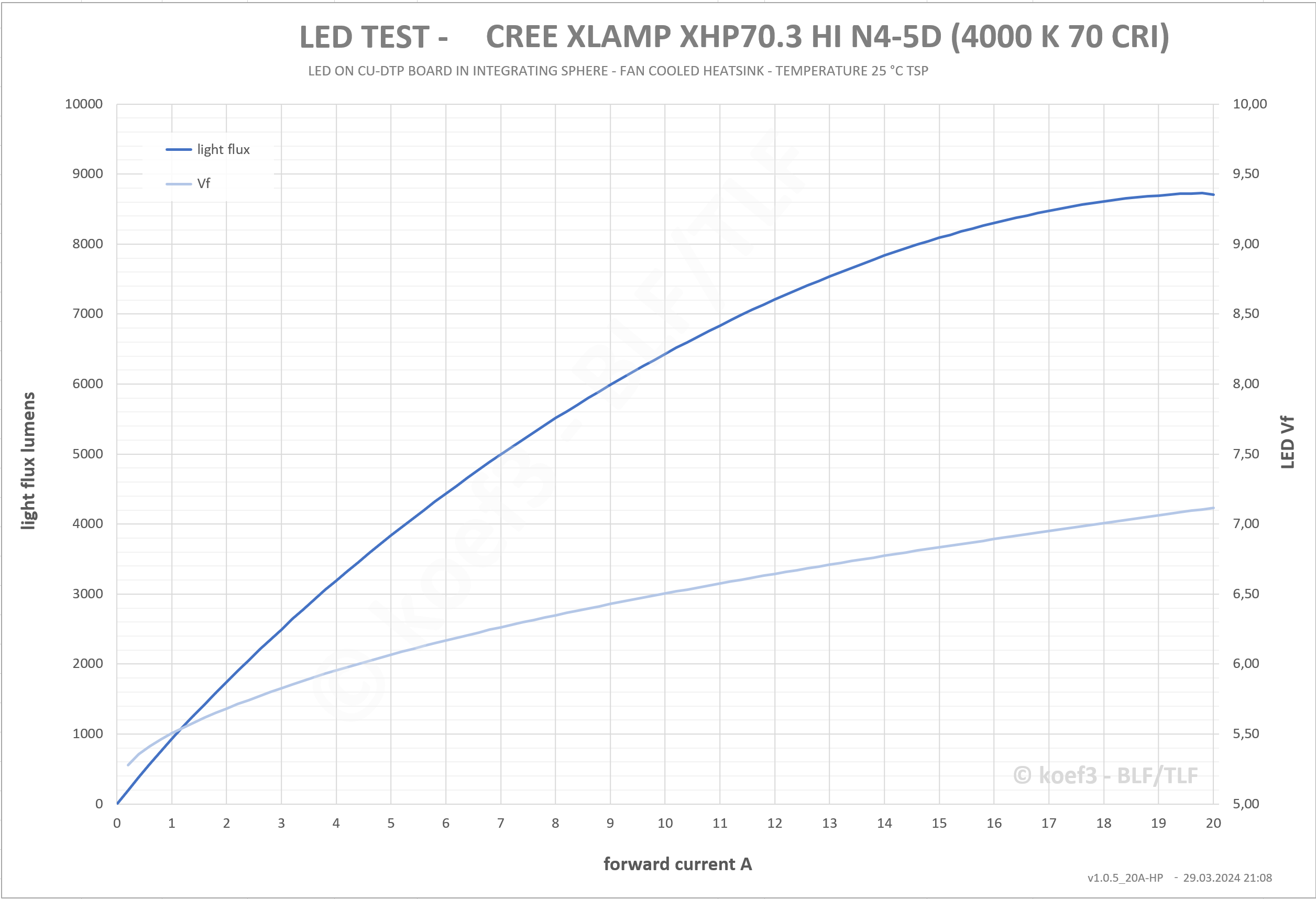
source : Koef’s XHP70.3 test
What we can see is that as current increases, the LED voltage (Vf), increases much more slowly, in other words, a small change in voltage results in a large change in current, and thus power or brightness. Furthermore, this is the current/Vf curve for this particular LED, for another LED, even a XHP70.3 from the same batch, the Vf will be slightly different, meaning that driving an LED at a certain voltage will result in different current with different LEDs even if they are the same model.
Worse : the Vf of an LED decreases with heat, meaning that as the LED heats up the current will increase, heating the LED even more, reducing the Vf and thus the current even more (positive feedback). For example, if I power an XHP70.2 (that’s what I have on my bench) at 6.4V, I initially get 5A, after a few seconds the current quickly increases to ~5.1A and reaches about 5.4A at 1minute, this is on a big heatsink which is much cooler than a flashlight, it would increases a lot more in practice.
Due to these reasons a constant current power supply ( strictly speaking, that’s what a LED driver is) is highly preferred for driving LEDs. That doesn’t mean using voltage regulation is impossible, but 2 main things must be done :
- calibration : measure the actual output (either brightness or current) of the LEDs and calibrate each driver for their coupled LED.
- temperature compensation : measure the LED temperature and decrease the output voltage as the temperature increases.
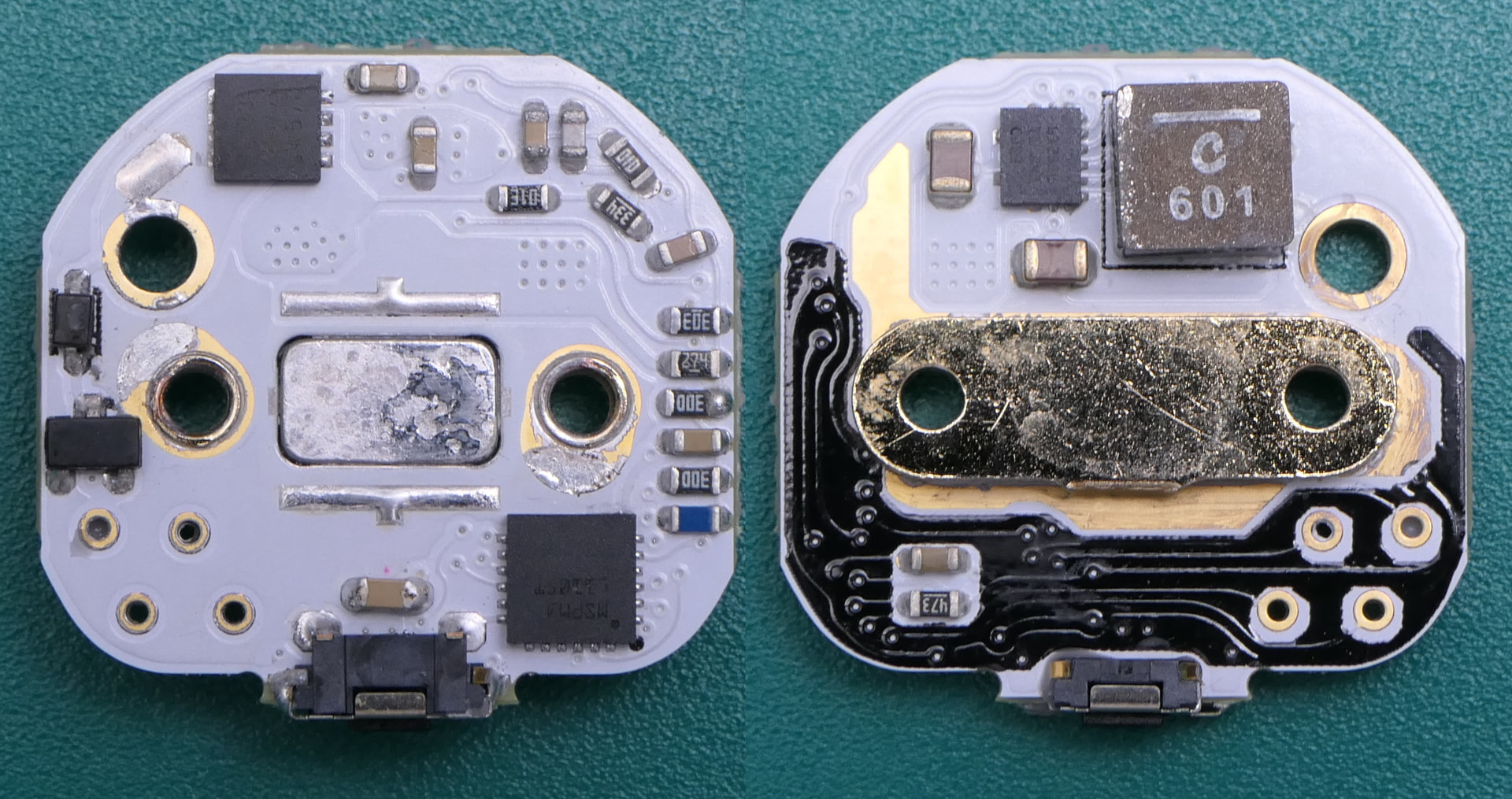
We can see the 4 plated holes on the lower left corner, these are connected the MCU and are very likely used to calibrate the driver for its LED while the output of some or all modes is measured.
So if this works well, what are the advantages?
- no power losses from shunt(s)
- space savings from no shunt(s) and analog components needed for constant current regulation, more so if multiple shunts were used to achieve high dynamic range (regulating from high to very low i.e. moonlight modes), MOSFETs are used to switch between the shunts which use space as well (you can see those in the lower left corner of previous Zebralight drivers in the 1st post of this topic)
- smooth ramping without the possibility of ’blip’ in the ramp that can happen with the use of multiple shunts.
In the case of Zebralight:
- bigger shunt used in previous design, resulting in bigger losses than usual, so more gains here vs a more common driver, reason is imprecise Op-Amp used (integrated in microcontroller).
- 4 shunts used in previous designs, where 2 can achieve the same result, same reason as 1), thus again more gains.
- no smooth ramping UI so it’s irrelevant here (i was expecting a smooth ramping UI option after this announcement but nope)
Onto driver analysis/testing starting with the components used :
- Reverse polarity protection MOSFET (front side, upper left) is a SiSS63DN (close to best available for 3.3x3.3mm size),
- MCU is a MSPM0L1105 (front side, lower right)
- Boost converter is a TPS61288 (bottom side), same as used in current SC65 and SC700
- Inductor is a XAL5030-601 5x5x3mm, 0.6uH, 4.5mΩ max
Testing is actually a bit challenging, usually I power an LED on an heatsink, wired to the driver under test with wires with a precision shunt in between to measure the output current. But doing this will change the apparent Vf of the LED, thus changing the output. I need to be able to precisely measure the output current without changing the LED nor the voltage it’s powered with.
So I modified the PCB a bit, cut some traces to add a shunt between the output of the boost converter and the LED, and routed the voltage sensing trace after the shunt so that the LED voltage remains unchanged.
Of course losses in this shunt are removed in the calculations ( I used 2 values, 5mR for high modes then 50mR for Medium modes).
An additional input capacitor was added for stability when powered from a regulated power supply.
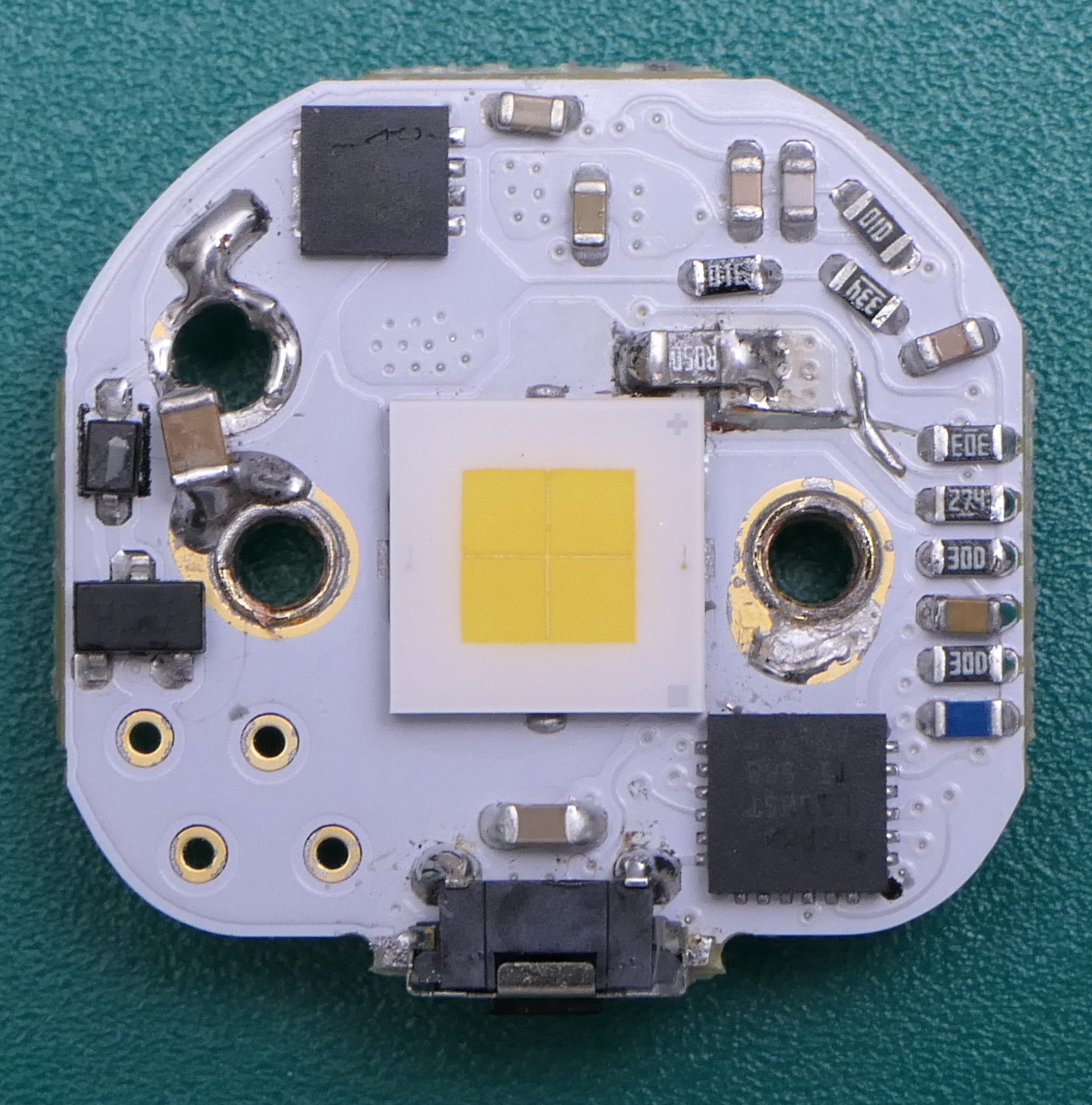
(also I accidently nicked a trace , fixed it afterwards
 )
)
Output/Efficiency results :
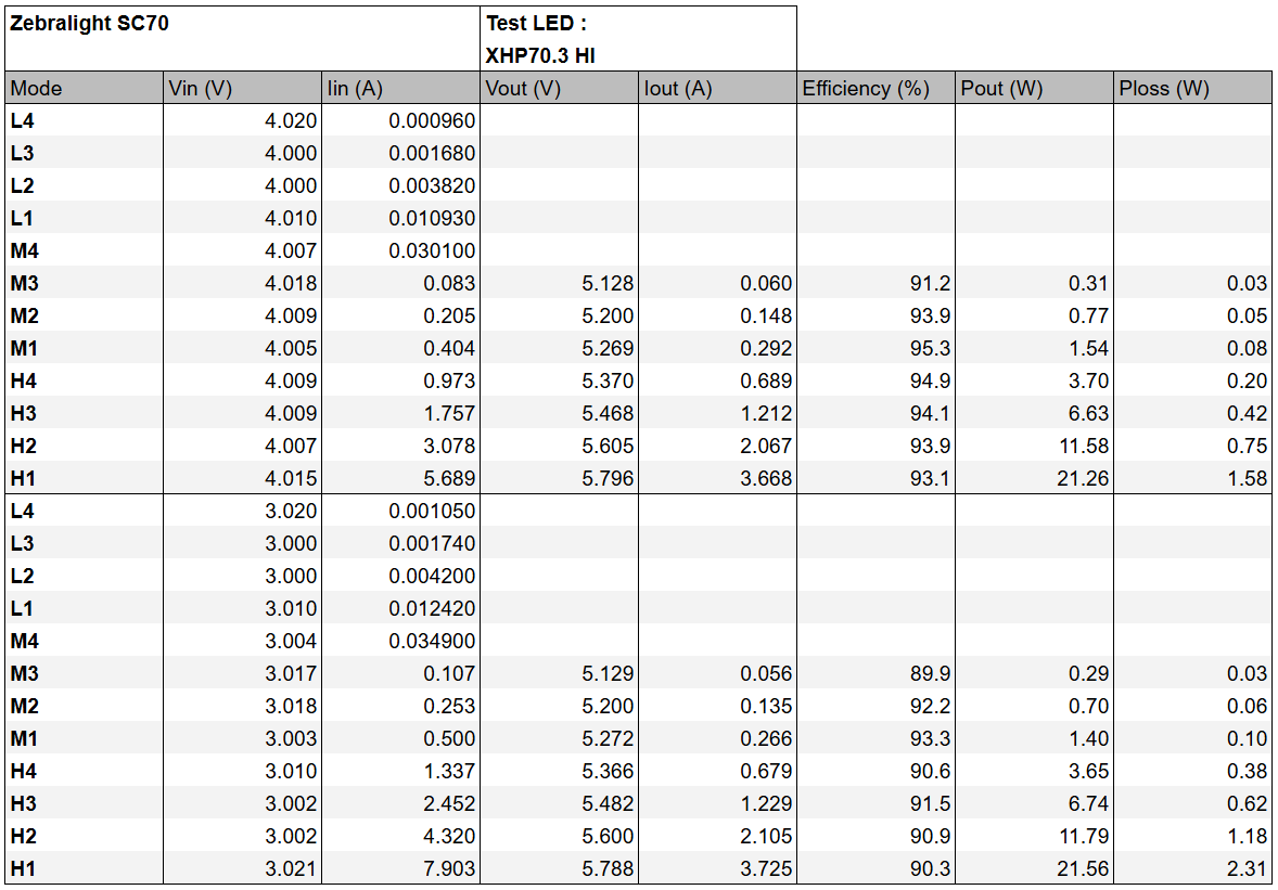
Output is measured is peak output, because after turn on, it increases a bit, then decreases a bit, this is the temp compensation being a bit under compensated at first, then a bit over compensated, I’ll try to plot this later (need logging capability on that output current measuring shunt), but overall I can say that the temperature compensation works reasonably well.
Efficiency results are good, but not as good as they could be, here’s one of my driver (with shunts) using same sized components for comparison (SiSS61DN instead of SiSS63DN, nearly identical, MP3432 instead of TPS61288, very similar too, same size inductor but 1uH) :
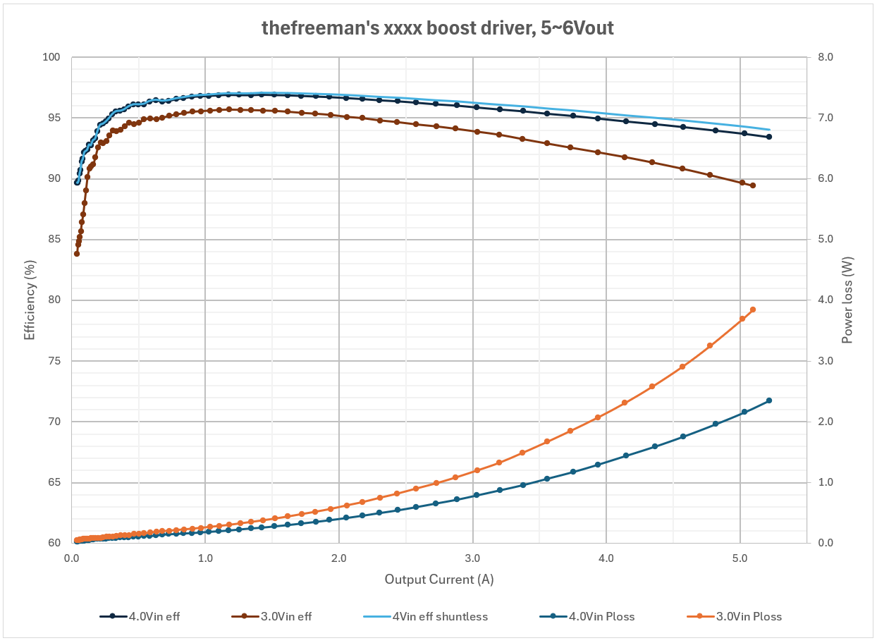
And its efficiency is higher despite having shunts, the main reason is the same as for the SC65 driver, the inductance value (0.6uH) is too low, for this output and size of components the best inductance value is around 1~1.5uH. Why such a low value was used? Probably the same supposed reason as for the SC65 (which should have used something like 1.5uH or even 2.2uH), because a higher inductance value decreases the switching frequency at low output and causes visible flicker in the lowest modes. It’s not an issue in my drivers (or Loneoceans’) because I use the MP3432’s ultrasonic mode which doesn’t go below 23kHz, at the cost of lower efficiency at very low modes, it’s a compromise thing.
Other possible reasons are :
- Some instability in the medium modes (and probably H4 3Vin, you can see the dip).
- The 400Hz ripple present in most modes.
- Low output capacitance, more losses in the capacitor ESR (equivalent series resistance) but probably minimal.
So there is more to it than just removing the shunt, and on my driver’s efficiency graph, I added a calculated “4Vin shuntless” curve, you can see that the difference is very small, only 0.6% points at 5.2A, 0.4% points 4A and virtually 0% at any thermally sustained output. I use a 40mV sense voltage at max output on this driver, for comparison the SC700 uses a 110mV sense voltage at max output, which would results in larger gains from going shuntless, but still not really big either.
Output waveforms :
H1 (max) :
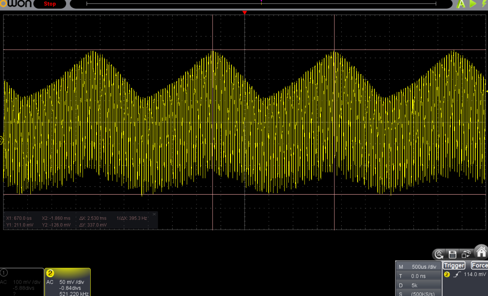
it’s stable, but there’s a ~400Hz ripple, this ripple is present in all modes (except higher freq like 1k in low modes) and comes from the filtered PWM signal driving the feedback pin of the TPS61288 to control the output voltage, actually there are two PWM signals, merged and filtered, one has a constant duty cycle per modes, the other is variable and looks to handle the temperature compensation, the issue is that the PWM frequency is very low and that the filter is not big enough to smoothen it, thus we see it on the output.
I tried increasing the value of the filter capacitor, this resulted in a big flash at turn on, most likely because the rise time increased, and when the boost turns on the voltage hasn’t risen enough yet, which tells the boost to aim for a higher output voltage than desired, hence the flash. A longer delay for starting the boost converter would be needed. Actually there is a small flash in L4 and L3 at turn on, likely same reason.
M1 :
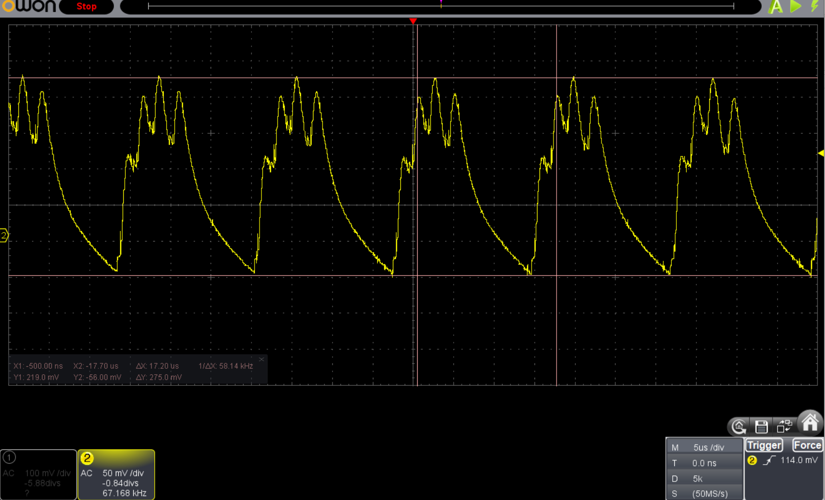
which is unstable with 60kHz oscillations, probably affects the efficiency a bit, but not hugely from the results.
Conclusion:
Zebralight does shows that you can make a LED driver with voltage regulation. The temperature compensation works decently well and according to light output measurements done by @Bob_mcbob it is fairly consistent between each SC70s.
But the main stated reason for doing this is higher efficiency and this isn’t really achieved due to inadequate inductance value and due to other smaller details.
So, to improve this driver, Zebralight needs to :
- increase the inductance value to 1-1.2uH, either use the MP343x in ultrasonic mode instead of the TPS61288 to get rid of low modes visible flicker that would result from the higher inductance or add a resistor load to increase the minimum frequency (would also cost some power but less than ultrasonic)
- Get rid of the ~400~1000Hz ripple by increasing the PWM control signal frequency and/or bigger filter.
- fix the low modes startup flash (probably) by delaying boost turn on (more).
- Fix instability issues in medium modes, probably tweaking boost compensation.
- increase output capacitance a bit (minor).