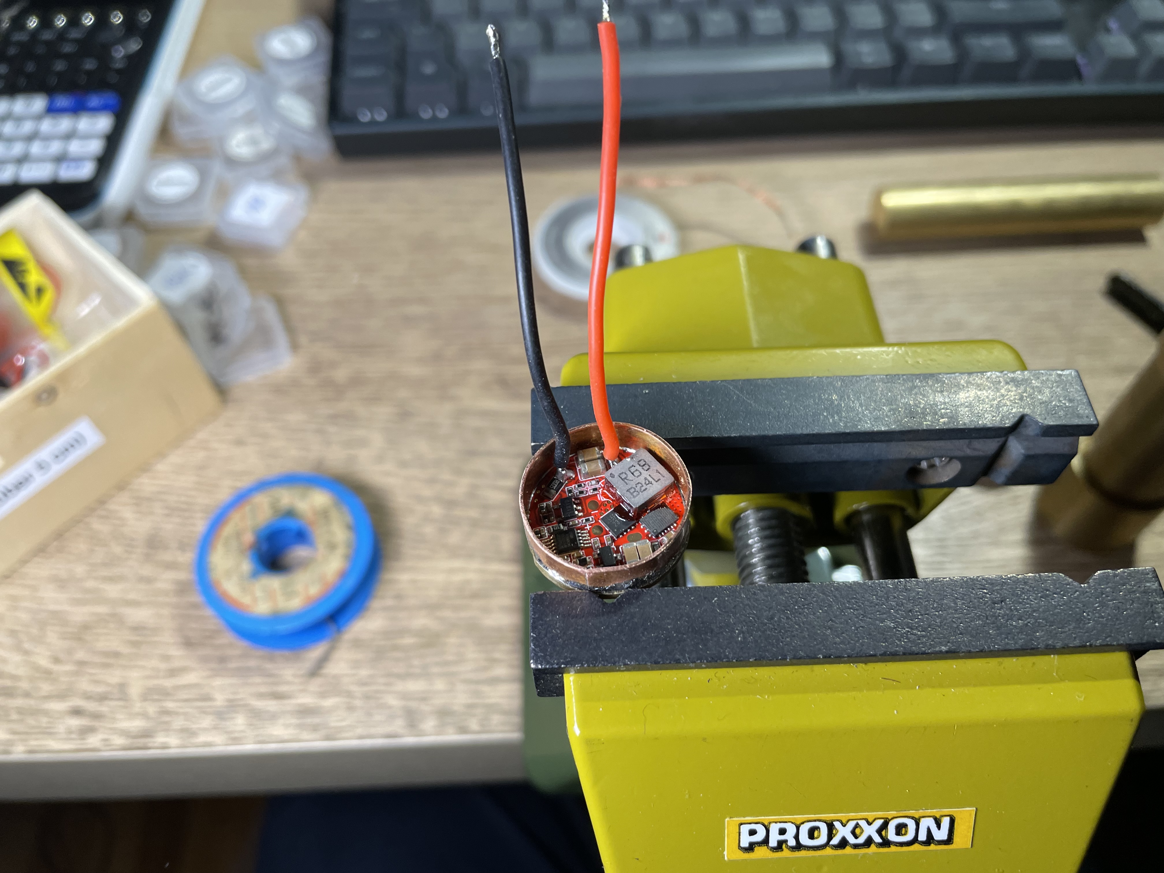
I prepared the driver, which arrived some days ago.
I will use the Convoy 8A Buck driver with 22 mm diameter, which can give in theory around 1800 lumens with 3x 519A R9080 LED.
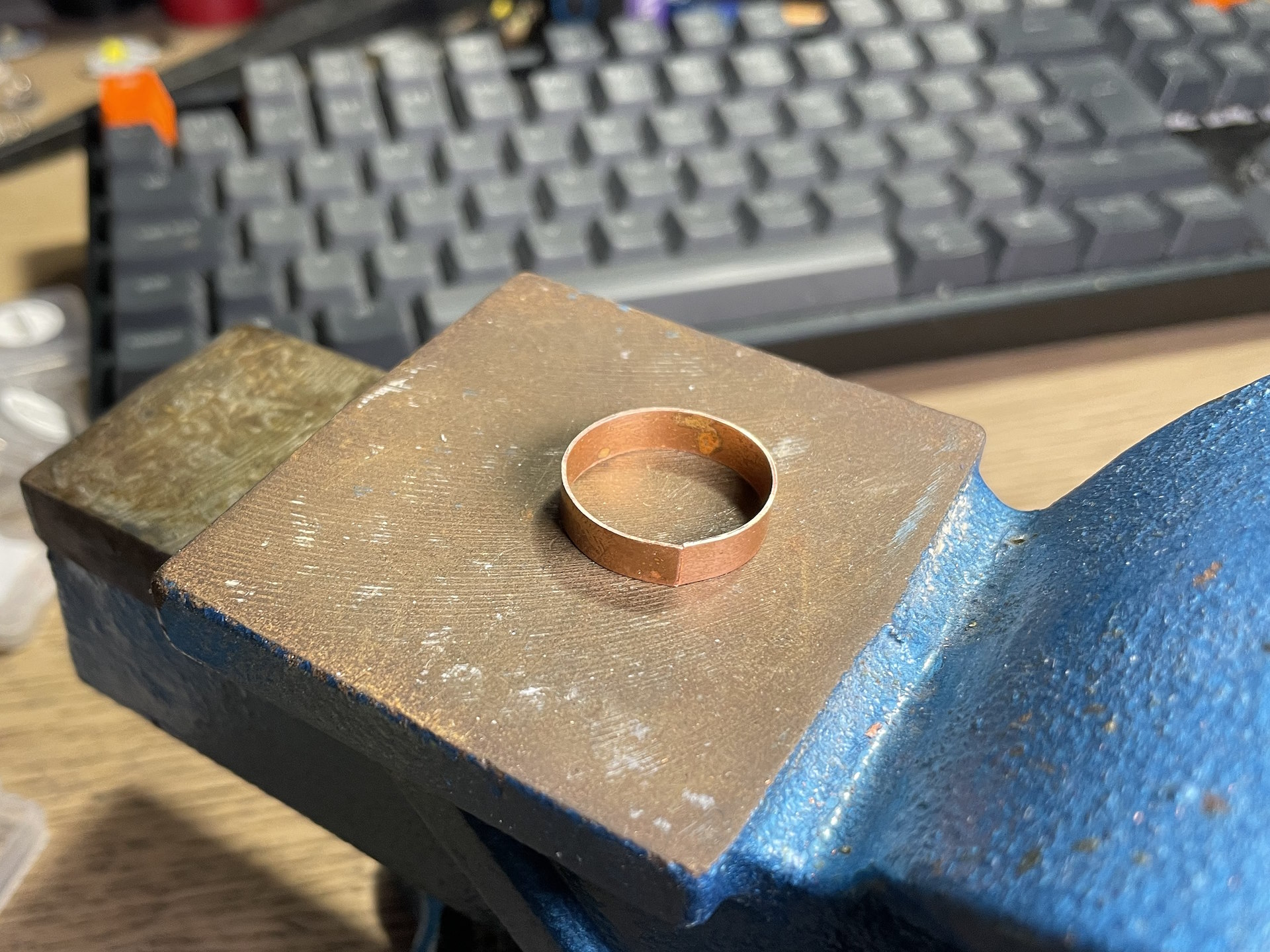
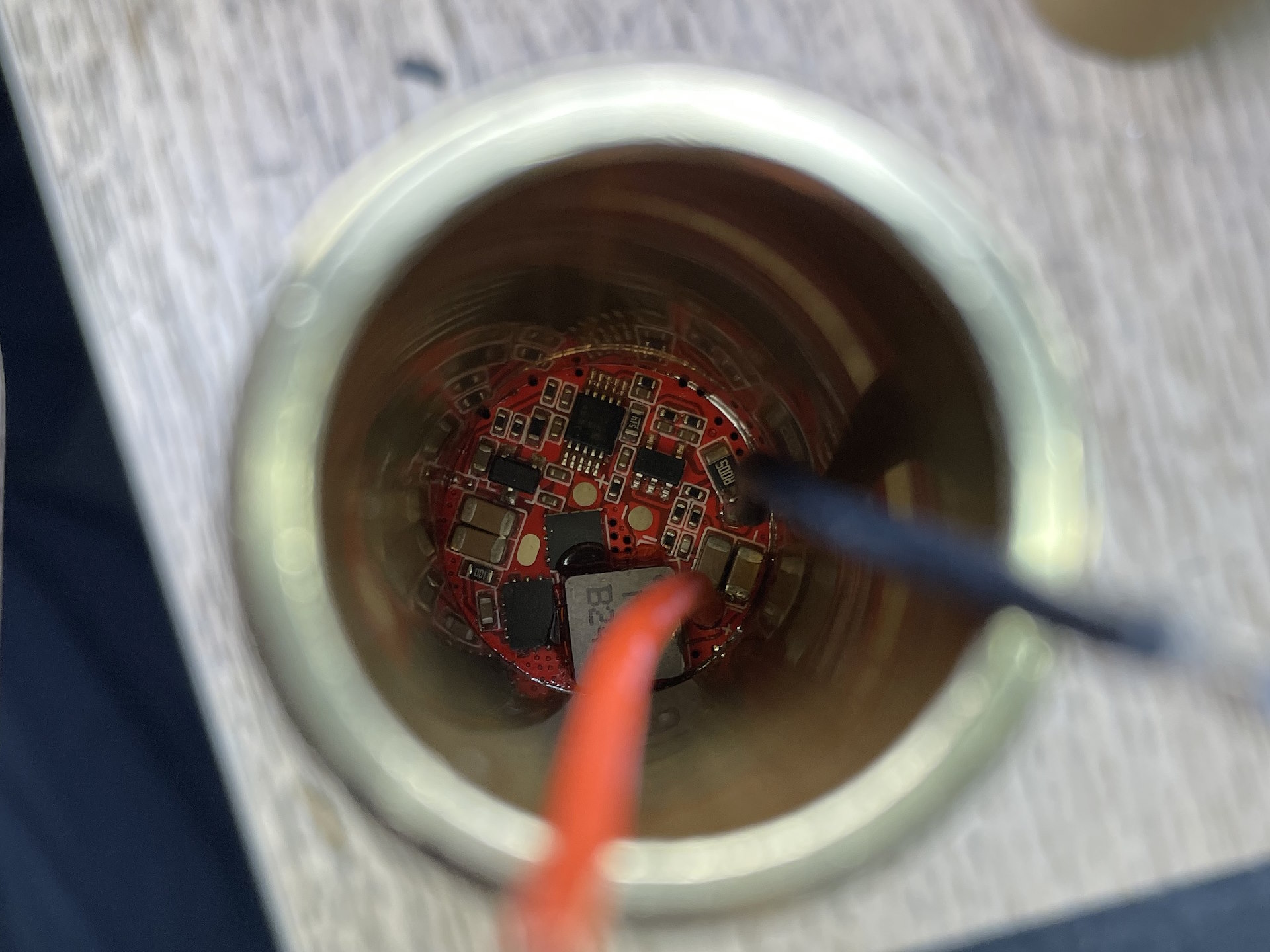
I made a ring from 0.5 mm thick sheet copper. This was soldered to the outer contact of the driver board. The ring is needed to ensure that it is fixed to the fittings.
Working fine
First test:
I hope to make the brass pill/heat sink in the weekend.
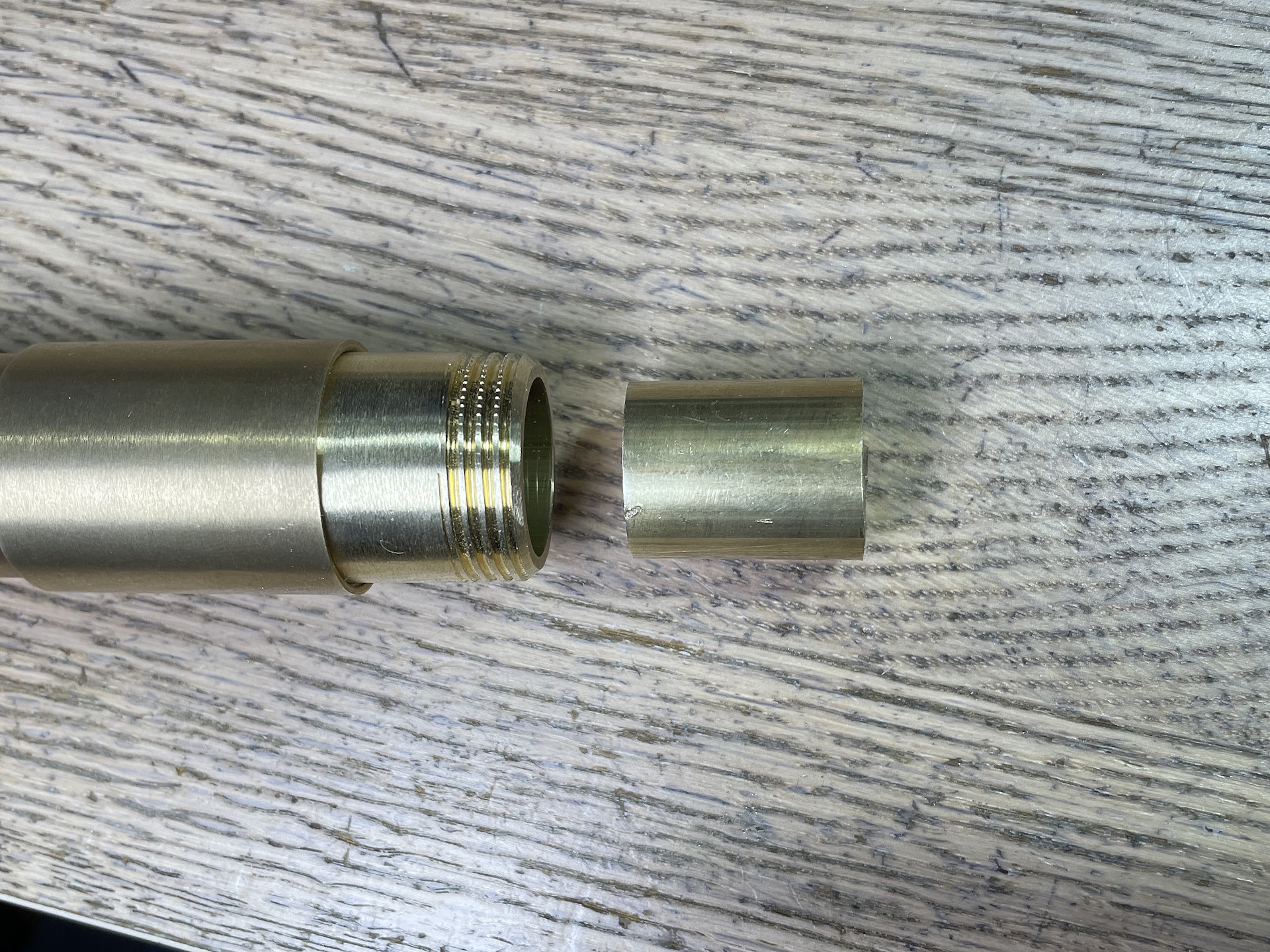
Among other things, I made the pill. It was important here to achieve the tightest possible connection to the outer tube. Beforehand, the newly purchased fitting was prepared accordingly in order to be able to accommodate the bezel correctly.
Although the seller advertised the brass round material as having an outer diameter of “20 mm”, it was actually 20.3 mm
Unfortunately, the “Made in Italy” lettering did not survive the grinding of the outer surface - it was not engraved deep enough…
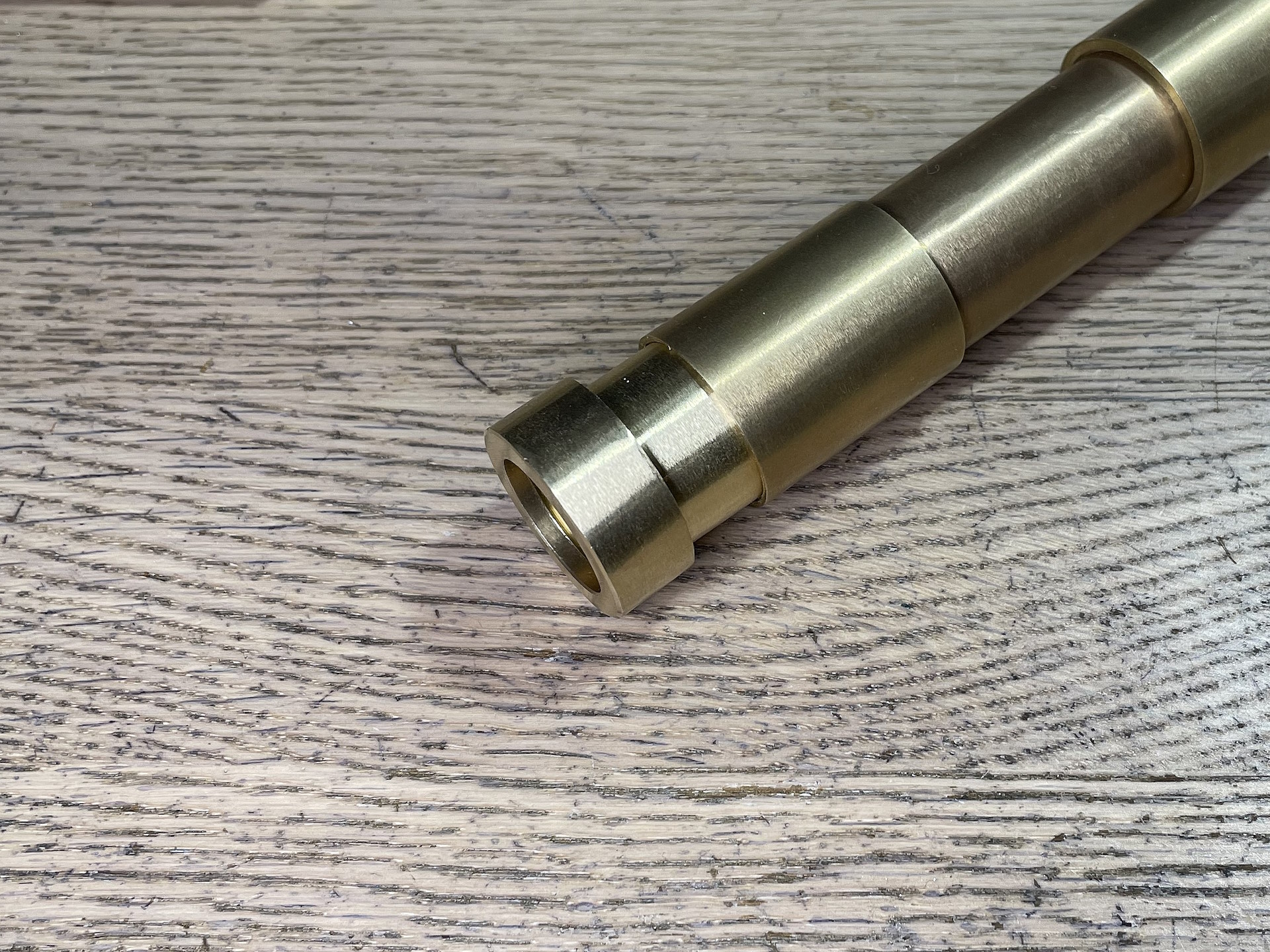
It took forever to grind the outer diameter correctly and, above all, evenly round (!). Here the pill is ready to be hammered into the fitting.
After adjusting the outer diameter, it was hammered into the fitting as carefully as possible. A 2-cent piece of our good old euro currency was “modified” a little in the process
The maltreated 2-cent piece lies there
This is what it looks like with LEDs.
The crooked soldered LED has already been corrected.
Driver and lenses with front glass installed.
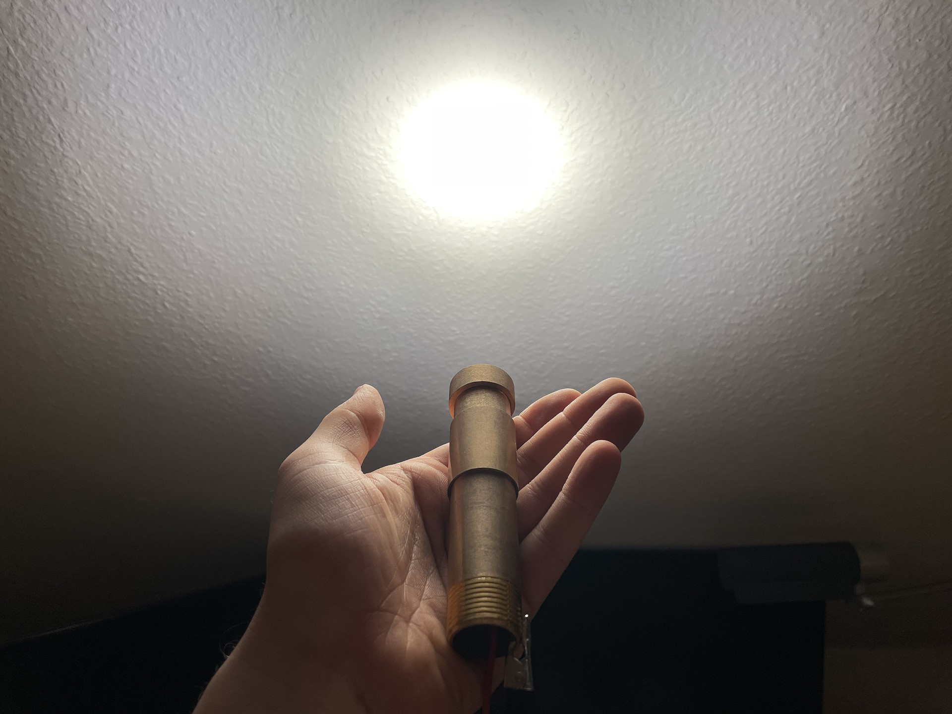
Now here is the first test ever, with power supply - and it lights up.
And it lights up well. With max. 7.8 A (here with 2.1 A)
Now only the switch needs to be installed. Overall I’m absolutely on track with my concept and the building of this light!
It’s not uncommon to find items advertised as some even-numbered size to actually be a little over or undersized. At least if oversized it can be sized downwards, but it’s hard to make something bigger. Looks like your great effort was well rewarded.
Yes, but not as much as with most other flashlights since there is a lot of thermal mass behind the LEDs. (Pill and outer casing)
I think after one or two minutes it will be too hot. I think 1600 lumens are possible with this configuration. Not as much as 2000 lumens, but it is more than enough to light up the dark.
21700 does not fit unfortunately, since the inner diameter of the fitting is too low and it is not good to drill it wide open, because it is likely that it is weaker and not as stable.
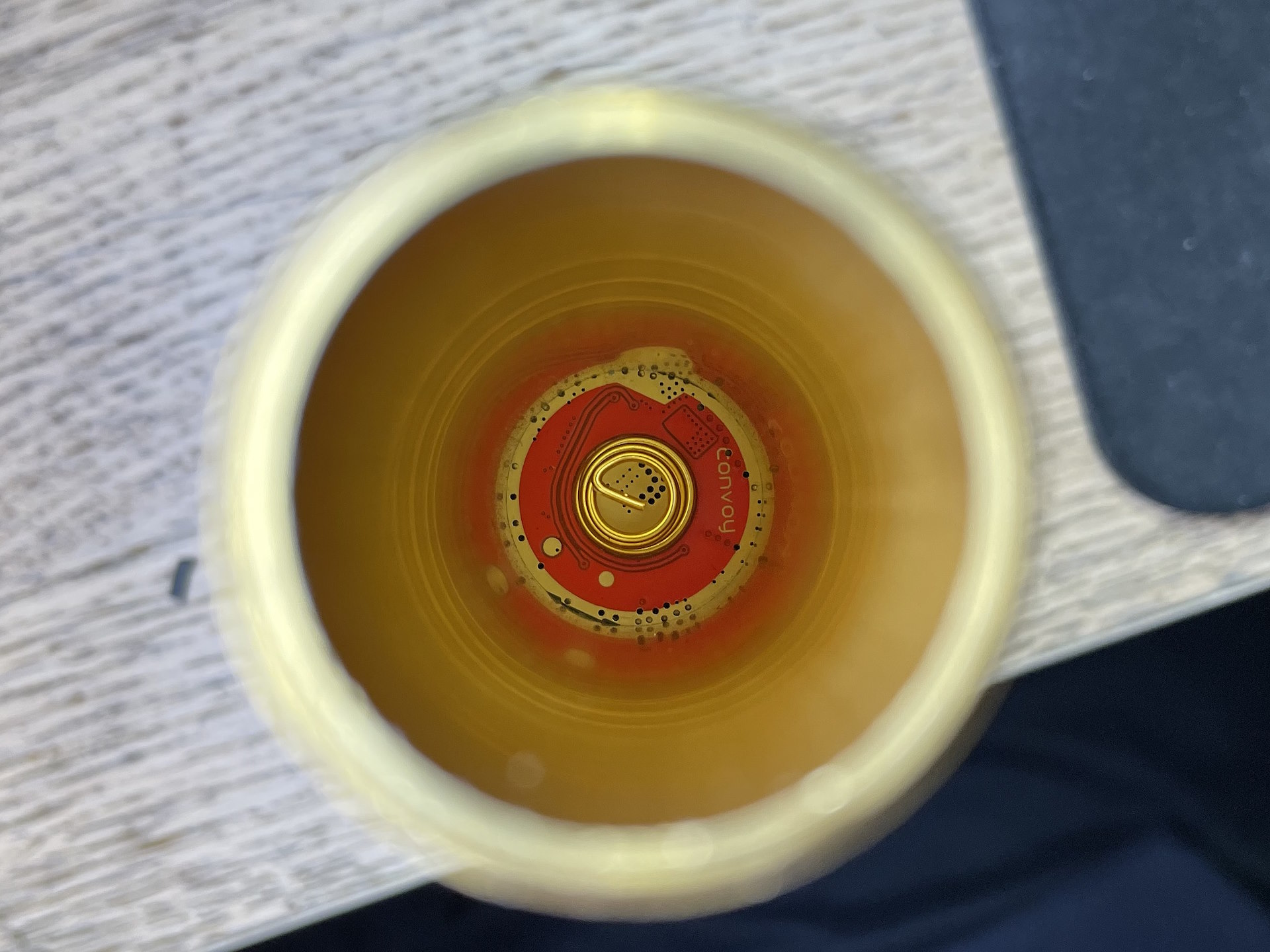
I built the tailcap switch today. (No, my project is not dead. )
Unfortunately the originally planned stainless steel switch doesn’t fit in the tailcap properly, so I had to switch to oldschool rubber switch cap.
Unfortunately, my cheap drill bit was really messing around, so my small rotary tool had to save everything again…
The tailcap is built the classic way. My goal was to keep the design reliable and simple. The switch PCB is held by a brass ring like in many other flashlights. It was made of a piece of my fittings.
After that I grinded some edges in the ring, so I can turn it in.
The switch PCB is self made. I don’t have any PCB that is in the same size. I used FR4, of course.
This is how the PCB looks now.
Built into the tailcap. Now the tailcap is working fine!
Thank you I already used this light as primary light source for a longer walk. I am not really happy with the FET based driver, but one day maybe I am able to get a 22 mm boost driver with proper regulation and - maybe - Anduril…
Maybe next year?
But beware, I have some new ideas in the pipeline for the 12th OL challenge