Pretty crazy all the same. Keep us posted.
My first efforts are usually unfit for public consumption and this was no exception. Thankfully with this hobby I get as many second chances as I care to try(I’m visualizing Bucket’s pile of reflectors with gratitude). Down the road I might want a driver with ramping for this light.
This one turned out unfit for consumption, public or private. No smoke, no sparks, no nothin. I think I’ll have to cite poor implementation of a questionable idea. I’m not canning this idea but for now it goes back on the shelf. I’ll be using an earlier 3A 7135 version without lvp to finish the contest light. This weekend is my last opportunity to finish and I have too many other fish to fry. Tbh, I think I’d rather have regulation anyway and the mtg is so stupid bright it hardly needs DD.
GL on the comp build RBD. Once the comp is over maybe the thing to do is attack your built board w/ a DMM and see whether everything checks out as expected. A schematic may help - sometimes that’s what I need.
Thanks, that’s sort of the plan but I’ill need to fix my magnifying lamp first. At least there’s a plan b and none of the remaining work needs magnification. The regulator works fine I just screwed the pooch on this board. I knew it at the time but had my fingers crossed in vain. The problem with the low voltage mod on the 105C is the trace that needs to be cut is under the mcu. I suppose one could desolder and bend up pin 8 instead but to do any work at all on a driver I really need the lens.
To me it looks like LFPAK56 could be added to current BLFDD boards without major changes. The current BLFDD boards look to me like they've had the pad enlarged for the tab - the real tab on a DPAK/TO220 EDIT: DPAK/TO252 transistor does not extend all the way to the edge of the package. Using the footprints I've got, which seem to match the actual landing pattern, there is enough space to stack both footprints:
The GATE trace is 10mil and clears the pads by >6mil. If someone wanted to do a better job than me, I'd say they could get at least 8mil clearances with an 8mil trace.
That would be excellent wight. I looked at that board only noticing the reversal of the pads and thinking a jumper would be needed. Tbh though, my to do list has eagle moving up rapidly so I can do this too and implement my own quirky ideas.
I’d be happy to make the tweak for you, but if you want to save the project for yourself that’s fine w/ me. ![]() I don’t have the BRD/SCH files for the BLF17DD, so if I was going to do it I’d drop Mattaus a line and ask for them.
I don’t have the BRD/SCH files for the BLF17DD, so if I was going to do it I’d drop Mattaus a line and ask for them.
The more I look at the footprint he used the more I wonder whether he wasn’t allowing for some even larger type of FET. If so, I think we can safely say by now that larger than TO-220 EDIT: TO252 is not necessary.
Be careful what you offer. Matt volunteered to help me with the Tiny10 and just look at where that led. I’m not yet feeling compelled to do everything on my own. More that the combination of the voltage regulator, this specific FET, and the lvp mod might take this version far enough from the norm not to want to bother anyone to help with something so unique to my needs. If your offering though, The ideal layout would include the at tiny footprint, pads for the LD2981 voltage regulator and it’s two caps(one on input, one on output), D1 with a separate trace for R1/R2, the footprint for this FET, and a generous path for led+. Placing the led pads opposite on the board is generally a good idea and being one not yet set up for flashing, I suppose the star pads are called for. All this makes for a layout different enough from any of the current boards to maybe just start anew but although I can follow a trace layout and pick and poke around I haven’t had to do one for myself so who knows.
Still interested? ![]()
Ehhhhh - I gotta keep it real with you: not so much :bigsmile:.
Already on my to-do list is to lay down some boards with a voltage regulator. That’s not really at the top of the list though. If what you have is pin compatible with other similar regulators then those projects are automatically related. At that point it’s just a matter of whether I ever get to it.
Today I worked on a new board which everyone will hate ;-). I did go ahead and implement the DPAK/LFPAK56 combined footprint on that board, I’ll post it in a bit.
The LD2981 is a sot-89 package with a low enough dropout to be suitable for 2S. I was attracted to it by the pin compatibility with the 7135. Vin is the same as Vdd, Vout is the same as Led-, Gnd=Gnd. A Zener board with the lfpak 56 and lvp mod would certainly be suitable too. It’s not something I’ll lose sleep waiting for that’s for sure.
Ouch, I forgot that you’d purchased them in an SOT-89 package. I took a glance at the LD2981 and in the SOT-23-5 package it probably is pin-compatible with other similar regulators such as MIC5235 and LT1761.
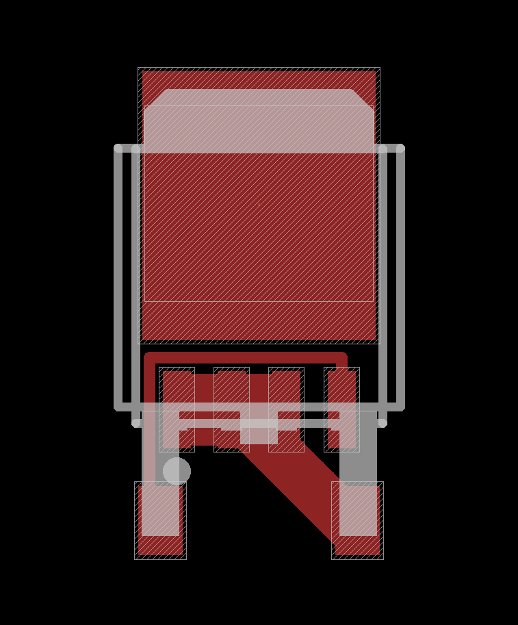
Here’s what I’ve been working on today that includes an LFPAK56 footprint.
I only have a few of them which is part of the reason I am willing to do such perverted things to a 105C board rather than ask anyone to design a board to use them instead of the Zener. Speaking of perversion, you are one sick puppy. I’d hate to see your plate at the buffet. That board is stuffed.
If I can’t build it I won’t be ashamed.
… although I suppose we just established that I’m shameless. ![]()
It’s good that you only have a few. As I said, the LD2981, MIC5235, and LT1761 all seem to be more or less pin compatible in the SOT-23-5 package. That’s the package used on the Knucklehead board. Microa pointed out that the datasheet for the MIC5235 only calls for a single 1uF cap + the chip is cheap. I’d bet a dollar to a donut that they’ll all operate with only a single 1uF cap at low current levels. Whether or not I do any more with the Knucklehead, I have 3x of the revised boards I did and 3x of the original 3.0 boards with inadequate heatsinking. There is no way I’d build the OG 3.0 boards, so I can use them just to play around with SOT-23-5 voltage regulators. I’ve got 7x of LT1761 or MIC5235, I forget which…
2 years ago I knew much less than the little I know now. I was looking for a sot-89 with less dropout than the L78L05 which was fine for 3 cells but had too high a drop out for 2. I’ll use them or not on weird projects like this one then switch to the Zener unless something better comes along.