From what I can see he didn’t release the schematics for the GXB172. Or have I missed it? Can’t find it on his webpage.
Mike, I dont see it yet but it look like the page is still ‘in progress’? I hope it will release soon. The old driver (gxb17) has schematic: GXB17 - A 17mm Single Cell Boost LED Driver
moderator007, yes! I am also going to build my own and hope it go ok. I ordered the pcb on oshpark and will use convoy host for body. Should I use Nichia 144 or XHP50?
From the OP:
I haven’t looked at this lately. But, if the above quote can be presumed to be still true, the firmware is not based on anything we know of. Just the hardware is compatible with BLF firmware options. Still, it would be nice to have the source to his “simple firmware” so that the “non-trivial modifications needed to work with this driver” can be considered fully.
For the simplicity and the higher output, I would go the XHP50.2 for the Wow factor. But a 90CRI 144 would be a good choice as well with slightly lower output. I guess it depends on if you want max lumens or Excellent color rendering. You can’t go wrong either way.
YMMV but I killed 2 dies of my XHP50.2 in a Mountain Electronics boost driver with much lower current. Not sure I would trust that brass pill for such a finicky LED.
What kind of amperage where you running?
So you think that you cooked it due to poor heat transfer? Did you flow the LED yourself?
It was the highest configured Mtn boost option. I guess 4.x @ 6v? I cant remember if i did the reflow or not. It was in a mini c8 (jaxman m8). I had been trying to get more heat xfer to body applying paste to pill threads and stuff and testing turbo on second highest heat stepdown in firmware.
It did survive several turbo cycles before this but ultimately ended up losing 2 dies somehow… idk
I have a shaved one that i used much harder with a 7-8amp buck driver in a Z1 and it never died. Apples to oranges though…
The brass itself is probly not what killed your dies. In most cases the thermal path either between the LED and MCPCB (most often) or between the MCPCB and the pill is what causes this (when your using a regulated type driver especially). Often on budget lights the pill surface is not perfectly flat, so a trick you can use is to reflow solder the mcpcb to the pill for a better thermal path vs epoxy, you still want to keep the layer pretty thin though. The mountain driver max is 4.2A which should be sustainable until the time you start to burn your hand with the light if all the thermal paths are correct.
Hope this helps ![]()
I guess my point in mentioning the brass was that I could never get the host hot enough to burn my hand before it stepped down. The driver itself would overheat before the heat path could do anything useful. Agree with all your comments though, cheap host requires a lot of tricks to make it work optimally.
Hello loneoceans, for pogramming your atmel microcontrol, I see on your webpage you use your 'pogoprog' programmer. Is this somewhere I can get this from? Do you have oshpark link like your gxb driver?
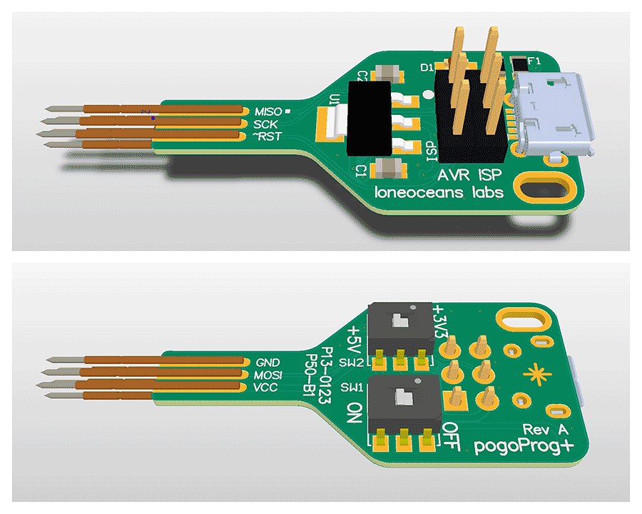
I think this is good for programming small board. thank you.
Happy new year to blf forum! I have got parts and waiting for pcb for gxb172. I will try to build one and see how good it perform!
I have all the parts needed and the pcb’s. Doing a lot of prep work to hopefully make soldering and reflowing these small components easier.
I enlarged and printed off all relevant pics and list on the GXB172 ,so I didn’t have to keep scrolling on loneoceans page to reference parts and their locations.
After OSHpark sent the email stating the pcb’s were being sent to Fab, they came in the mail a few days later.
Good to know we have both crawled down the same hole. I might need some guidance. ![]()
Maybe we will both come out shinning our new GXB172 boost driver flashlights. ![]()
Also have a copy of GXB172 and the parts for the 6V BoM, and will be embarking on a similar quest soonish.
I’m also interested in the schematic and source code, as I’d like to know how the opamp/current sense works in detail (esp with the DAC output, which I’m assuming is used to change the current output?).
I have looked but have never come up with anything. Hoping he might publish this at some point, it would be of great help.
I got the coil side completely populated and reflowed. Working on the spring side now.
Hoping I don’t have problems trying to program the 841 with avrdude. From what I have read it’s not supported and needs a patch in the config file.
I may end up having to buying a new programmer.
I explained it a few times already, but in other threads (and PMs). Can’t find it right now though.
You should be able to find out yourself what it does, but if not, the OpAmp essentially acts as an inverting integrator. With it comes some drawbacks in controlling the current, but it’s the only simple solution that I can think of (which is “independent” from the LED voltage).
And please don’t call an RC network a “DAC”, its a filter.
moderator007, I just want you to know we are applying the kid’s birthday party rule set to this.
If you make one for yourself you have to make one for everyone in the thread, it’s only fair…
I’m no professional at this, just a hobby. I’m just hopping I can actually make it work. ![]()
May the soldering gods please shine on me. ![]()
0402 size is no joke, they are small that’s for sure. Not much bigger than a grain of salt. :person_facepalming:
I just want to comment on the XHP50.2. I don’t think it’s bad heat path that kills them. I had 4 out of 7 fail in my 7xC8 light, all came on 20mm noctigons from MTN, running 5A or so each for just a few bursts. Unfortunately they just seem fragile and/or bad process control in their production.
Gotcha. I’ll take a look!
I’ve gone so far as trying to diagram the circuit, starting with an opamp in a basic low-side current sense config, then attempting to hook in a “control” signal to see how that affected the output, along with tying it with the nominal voltage set network. Futzing with various resistor values from the BoM, I did manage to get something that output 0.5V, but seems a bit overall magic to me.
Hah, my apologies. I’m not a EE so I’m mostly winging the terminology here. ![]() It’s a low pass RC filter on a PWM output from the ’841, then, yeah?
It’s a low pass RC filter on a PWM output from the ’841, then, yeah?
You should be able to run ```avrdude -p ?``` and it will tell you what chips it’s configured to support. I’m running whatever is in the latest version of Ubuntu, and was able to get the given .hex file programmed after only populating the bottom side. Command line looked something like this:
I’m using a USBTiny ISP as the programmer. No mucking about with fuses, just use the defaults (as he notes in his instructions, IIRC).
If you have an Arduino environment setup, you can download support for the ’841. Look for ATTinyCore in the boards manager. Since we only have the hex file, I’m not sure that you can actually use Arduino to program the chip, but you should be able to compile an empty sketch, grab the avrdude command from the log output, and try to use that to program the hex file Lone provided.