I intend to mod a UltraFire F13 with MT-G2, zener modded BLF X6 driver and 2 of the new 26350 cells. The shelf (correct word?) where the LED MCPCB gets placed is anodized. Since the MT-G2 produces lots of heat - is it necessary to remove the anodisation there?
If yes - this light has no pill (integrated), the head is pretty narrow, the shelf deep inside and I don’t have sophisticated machining tools. What’s the easiest way to remove the anodizing then?
This isn’t answering your question but if I may ask one. What are all the threads like and where did you buy it from. The last ones I received along time ago had terrible threads and this has put me of buying any more.
Some will say remove the anodizing. I use Bleach but it would be very hard to do that on the shelf without ruining the rest of the anodizing. You could try some emery cloth or wet and dry paper.
The threads are not beautiful at all but once the light is assembled I only have to screw the tailcap and with lots of grease it’s ok. I like the form factor of this light, it has many cooling fins and it’s cheap. The reflector hole for the LED is only 7 mm thought, I had to widen it for the MT-G2. Bought the F13 at Gearbest.
Thanks F M. It doesn’t sound like they have changed from the last lot I bought. I’d be interested to see pictures of the beam pattern when your finished.
Don’t worry about the anodizing.
Anodizing interferes with thermal conductivity. If you were going to push the MT-G2 to the edge, I would remove it. With those cells, you will probably only hit the 5's (Just throwing out a number. I haven't compared the Vf of the LED to the voltage sag charts of the cells to get a real estimate). So I wouldn't worry about the anodizing. You should uses a flat disk and wet sand to make sure the shelf it somewhat flat. That will remove some of the anno, but it's pretty tough to sand off anno off an integrated shelf.
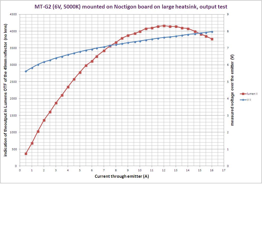
EDIT: Looked up the charts. Looks like you will briefly do 10ish amps, but probably won't that last long enough to worry about. Here are the charts with links to the threads:

What do you mean, “You should uses a flat disk and wet sand to make sure the shelf it somewhat flat.” I’ve been trying different ways to sand uneven shelves without making it worse. The best way I know now is to use a grinding wheel just over half the diameter of the surface. Then I try to keep it straight and sand it flat by going in circles. However, if it’s not perfect, it can go bad quickly!
^
That is how I do it to and what I meant. I use those grinding wheels from rotozip type packs. Yes, you can create a bowl pretty easily. When I do that, I used an endmill bit in a drill press to remove the high edges. Thanks for helping clarify what I meant.
Make no mistake about it, every possible trick you can pull to provide some thermal capacity should be employed. It WILL pull more than 10A, and it WILL get hot very fast, fins or no.
I have 12 MT-G2 lights and have played with many more. On an FET DD driver you will typically see 12A or so from a decent cell and it’ll get hot fast, make around 4200-4300 lumens, and have a beautiful color tint. The F13 should have a pretty decent beam profile as well.
If you can pull it off, I’d go with bare almuminum under the copper mcpcb. I’d even add some copper under the shelf if possible. Contact being most revelant, any copper added will need to be semi-press-fit to the sides to get the heat out to those fins.
You’re gonna love this light, I’m betting on it! ![]()
Edit: My Convoy C8 MT-G2 likes having the reflector on top of the substrate. Others I’ve done like having the reflector all the way down on the mcpcb. I’ve cut the L6 reflector aperture into a square to sit down over the entire MT-G2, sitting on the mcpcb, and the beam is much better than I expected. So you might have to play with that some. ![]()
^
Listen to this guy. He knows way more than me about driving emitters DD from various types of cells.
I have an Astrolux S41 which has an anodized tube and threads screwed into the copper head. The copper head gets hot very quickly, but the tube takes a while. I swapped in a tube from an unanodized BLF A6 and the heat transfer is much, much better. If you have anodizing in the thermal path, you will want to get rid of it.
Hhmm. I'd like more info on this - I just looked and can't find something that has a true flat surface, and be small enough. Any links or pics? I've looked around before and could not find anything. Everything i see has a screw head in the middle. I gotta be missing it.
I've been using a strip of sand paper, wrapped over the blunt end of a metal chisel or nail set, and do it all by hand. Sometimes it takes too darn long.
Thanks for all the help!
I meanwhile managed to remove the anodizing with a flat grindstone in a dremel. Not easy but the surface still appears even.
Next problem I just noticed: the shelf where the MCPCB lies on is really really thin - not more than half a millimeter, I guess. I don’t believe it will work without a press fit copper plate at the driver side of the shelf (as DB Custom mentioned) which probably is already too much machining for me (I’m more the software and electrics guy).
Perhaps I should rather order a Convoy X3 for this mod …
I used something shaped like this, the stone is glued on top:
Not from that company though, I got a used dremel like machine with some tools a while ago.
Do I understand correct that the beam with the square hole is better than the beam with the reflector sitting on top of the substrat? Did you just file the square, won’t the silvering chip?
It is unfortunate that the shelf on the F13 is so thin considering the driver compartment is huge. When I built mine I used thermal epoxy (thin casting epoxy mixed with various grits of silicon carbide, but arctic alumina would work fine) to glue an aluminum cylinder into the driver compartment. Not as great as other mounting methods and I used a lathe to machine the aluminum but you could probably find something that is about the right size and file it down a little to fit. The thermal epoxy is good enough with that much surface area and the thermal mass really helps slow the thermal climb. Only have a DD XM-L2 in it but it does take a loooong time to warm up in turbo. Also packed thermal putty on the outer edge of the MPCB and up the walls of the reflector compartment, not great thermal conductivity wise but a lot better than air and adds more thermal mass if you don’t mind more weight. And I generally throw some cheap thermal grease on the body tube to head threads for good measure and in this case on that long shroud on the front too.
What is the diameter of the driver cavity? If it’s close to 19mm you could use pre 1982 pennies soldered together and press fit to add some mass to the pill. Some say this will not help, but I have had good luck doing this a number of times. I have compared two lights and the output drop from thermal sag was delayed in the light with the added copper. It most likely will only help in this way in the first 5mins of use, but many uses don’t last longer than this anyway.
Soldered a stripped mcpcb to the back of the LED mcpcb and packed silicone (ice cubes) into the driver cavity. Then the tail cap threads on the tube stripped out, POS! :rage: Removed the good stuff and the lens, and flattened it with a sledge hammer, :+1: or was it melted down with the O/A torch, :smiling_imp: cant remember? No it was the hammer, the F3 got the torch! That was awhile back! I still have the red tail cap boot somewhere? That was back when OL had a thread about them ? :cowboy_hat_face:
Nice! ![]()
I just use these with a square piece of wet sand underneath. I use my thumb to move the stone around the ledge with water dripping on it. Or, better yet, soap lather. You can rub two of these disks together to remove high spots. They have always been flat when new for me.