Help driving 3 XM-L2 with one (Nanjg 105c) driver

Hi all

i have modded a 3C Maglit to triple XM-L2 using this method in the pic below

well it have worked very fine but tell now this flash light have fried 3 Nanjg 105 drivers all 3 of them are giving low mod only now

well i decided to replace the 4th one but i was afraid to fry it either so i did some tests on this method

well at High the driver are getting 3.5 Volts

medium 5.5 volts

at low the driver is getting 6.5 volts

well now i think that is the problem that fried the 3 drivers , they are taking much volts at Mid and low mod

well what i was thinking is to make a zener mod for this driver to allow it to take higher volts . so can this work ??

thanks in advance

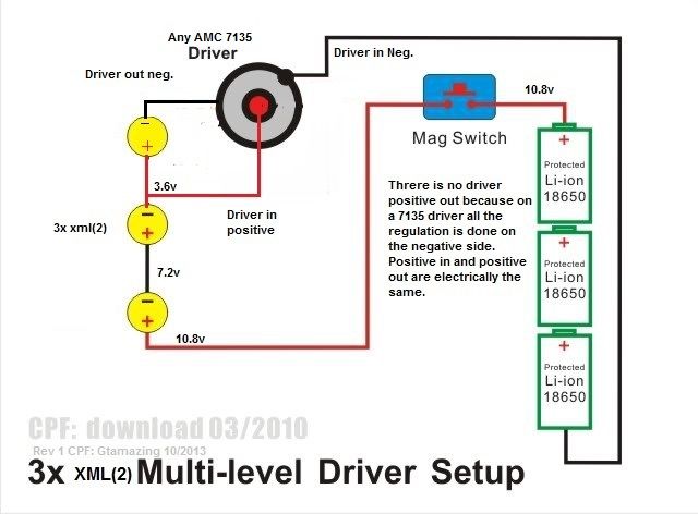
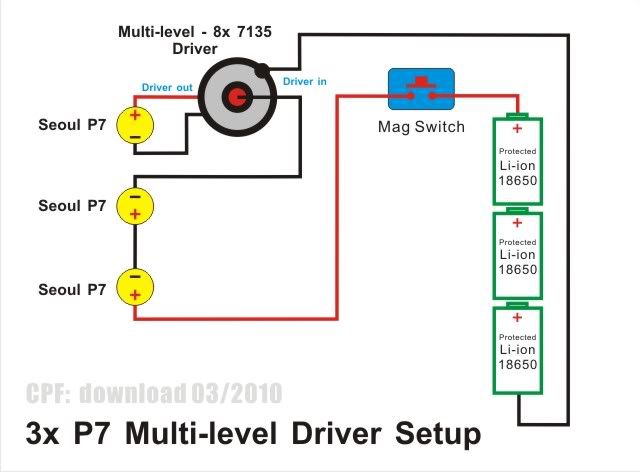
I don't think the wiring is correct. I am not familiar with that modification of the original done by user download @ CPF. I did the same mod here following the original wiring scheme below and have had no issues. If the drivers are getting fried, then V is too high. I would suggest to redo the wiring.

If I recall there was some difficulty using that mod with XML’s. Originally, CPFuser download did it with P7’s that have a higher Vf. I used a slightly different method Here see Post 100 for a picture and description of the mod. For 3 cells it used an L78L05 voltage regulator in place of one of the 7135 chips. Another less complicated method uses a Zener diode and resistor. Both methods fix the input voltage of the mcu and disable voltage monitoring.

A diode by itself in series should soak voltage by 0.6V so in theory it should work. But with low pushing 6.5V, after diode the driver will still get 5.9V, too close to the 6V limit for comfort. The voltage peaks will probably kill off the driver slowly.

Maybe a diode and a small resistor will work. I’ll leave the value calculation to the experts.

what if i added a resistor between driver neg & battery neg ?

That works but if you can’t switch it out you lose time in regulation.

sorry but i don’t understand ? what you mean with switch it out ?

That’s the high current path, so you’re just gonna lose a lot of power that way.

Adding the resistor before the IC power pin (for powering IC itself) should work similar to diode minus the reverse voltage protection.

By switch it out I mean an on-on-off switch. 1st on is with resistor, second on is without, and off.

i added the resistor but the driver still getting about 6.2 volts at low i think i should try Zener mod , but do i have to add the resistor in the driver

like this pic

or the zener is enough