two more apps to try
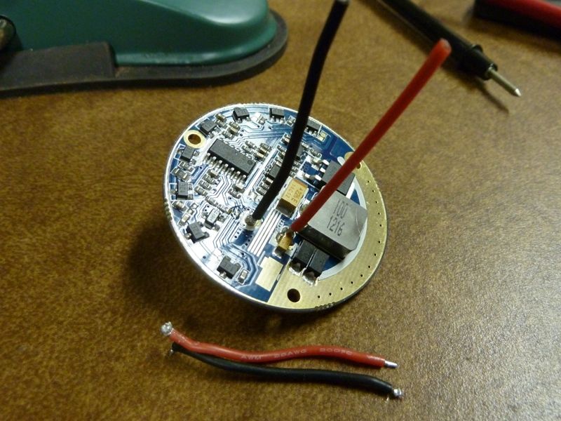
Pics on the cracked open TN31 and the tools I used:
http://s1054.photobucket.com/user/TomE2012/slideshow/TN31
Tom E, those are some real nice looking strap wrenches. How do you like them?
Can you tell me what brand they are and where you got them? Link if possible please?
Im getting tired of destroying a set of harborfreight strap wrenches every few months… take em back and swap them for more rubbish. ![]()
Thanks.
Actually manxbuggy1 did the research and found these with an aluminum frame - real nice, solid. Here for about $18 each:
http://www.amazon.com/dp/B0011E4QU4/ref=pe_175190_21431760_M3T1_ST1_dp_1
I wasn't worried at all of damaging the light because the thick rubber strap lies between the flashlight body and the aluminum frame of the wrench.
Update: I was desperate to crack open the 7G9 a while back, and went to HD or Lowes and bought a nylon strap wrench for about $30, it's solid too but the wrench itself did some damage, and was difficult to secure the nylon strap with a one hand operation. I find these aluminum/rubber ones much easier - really had not much of a problem opening the TN31, didn't need to use hot water or a heat gun either, and it seemed to have just as much caked up LockTite as the 7G9 did.
Thanks for the great recommendation Tom E. I just ordered a pair of Boa’s. I wonder if they would be enough to crack open the large bezel of a TK70? :bigsmile:
I also have a nylon strap wrench. It looks more like a cast iron pipe wrench handle with a strap at the end. Its great for holding rough metal but not so good with delicate aluminum.

Think that's the exact one I have, but in orange! Gotta pic of it in my 7G9 thread: https://budgetlightforum.com/t/-/14618.
I did the resistor mod and got a nice bump in lumens and throw, and am now finally getting around to the LED mod. I found the same kapton tape on the bottom of the star, as Alex described. here's a pic showing it after I partially tore it off:
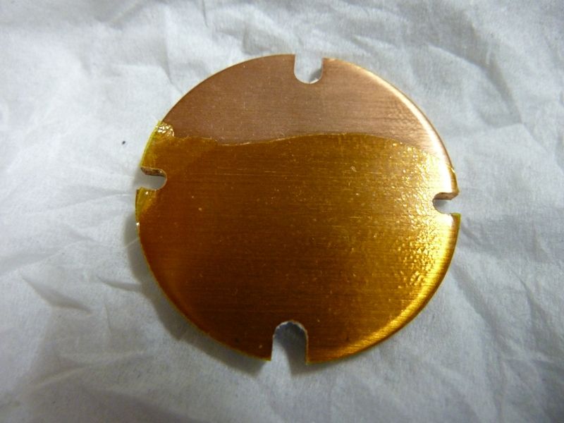
Also, I did a continuity test after removing the U2 LED, and found that there is a direct thermal path to the bottom of the star. It even looks like it's direct path by how the tracing shows through as the raised portion on the top of the star in this pic:
I don't know, I could be wrong, but I don't think there's a reason to dremel off a layer, or use a SinkPAD, at least on this one (mine). Maybe this changed? This copper star is 2mm thick compared to the 1.5mm of the SinkPAD, so if it could be kept as is, it would be an advantage, specially since you can screw it down and have more clearance for the wires. The wire clearance is even more important since I'm upgrading from 26 gauge to 22 gauge.
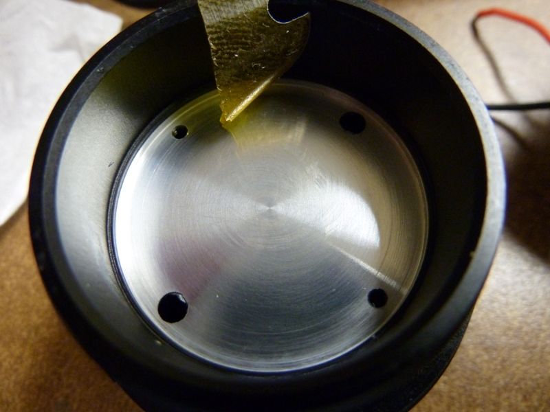
Here's a view of the machined pattern on the top of the pill, along with the piece of kapton I tore off. Also, that copper on the bottom of the star had a lot of ridge lines on it too. All this will be sanded to 2500 grit paper.
Here's a pic of the new silicone 22 gauge wire (from Hank at IOS), and the original 26 gauge wire laying in front:
Got an XM-L2 U2 1A (supposedly) soaking now in gas for the de-doming  . I'm thinking/hoping of getting 320+ kcd out of this.
Hi Tom, Have you cleaned up the heatsink plate or have they used Kapton tape 'Instead of' thermal compound ?
Edit - oh, realized I didn't answer your question directly - yes, the pic is after cleaning up the thermal grease. They used white colored grease, not gray, so it couldn't be AS5, could be Fujik, or could be another Arctice grease though, couldn't tell.
I sanded the heat sink (alum pill top) and star at 8 levels, up to 2500 grit, that's all, then I used AS5.
Oh! The gas de-doming only took like 2 hours, finished and tested. No battery carrier mods at all (yet), but using Pana PD's (not even fresh):
lumens: 1,332 at start, 1,275 at 30 secs
throw at best, measured at 4.31 meters: 347 kcd, which is 1,178 meters at 1/4 lux (moonlight)
So, got the results I was hoping for. Actually, the throw should be higher, and I'm thinking will be if measured at a longer distance like 15 meters, but not sure. Wow - it's really an intense beam.
Thanks very much indeed Tom, and congratulations on the fantastic results. I'm looking forward to your beamshots if you have any :)
Wow, that is some thermal insulation.
I have this terrible feeling that most of us are going to find this tape on the back our copper MCPCB's
Thrunite owner is aware but his response wasn't all too comforting. The language barrier is difficult and I'm not entirely sure he knew exactly what I was talking about first time I mentioned it to him.
After showing him this thread and the actual picture he replied with "I see the tape it is for preventing the anodized on the copper"
It should have been removed prior to assembly and I've highlighted the heat transfer issue but I'm yet to receive a further response.
MCPCBs are not being anodized...
Reading between the lines he likely meant to say Oxidized instead of Anodized. But nevetheless, it should have been removed prior to assembly because it's a serious QC issue
So he actually tries to explain why there is a high temperature resistance tape there on the PCB, even so that should not be there in the flashlight, also as I see there was no thermal grease anyway.
Ooops, if you are referring to my photos, there was thermal grease there, but I cleaned it all up before taking the picture.
Yes.
Ok, so you cleaned the head base and also the MCPCB yellow tape.
Yep - I cleaned up both sides for the pics. I mentioned in an earlier post they had a white colored grease there, could have been Fujik or a better Arctic grease, but certainly wasn't AS5. I love this design though - big, thick MCPCB screwed down with a direct thermal path in copper - better than the 20 mm SinkPAD's because it's bigger and thicker.
Sorry about that.
I do not think anyone uses Fujik out of the higher-end companies. As for AS5, I do not think anyone uses it, there are better alternatives from Shin-Etsu which is an industrial manufacturer (also OEM for others), you buy with kilograms and I presume that sort of grease can be use much better in a industrial manufacturing plant than a product that caters to retailing.
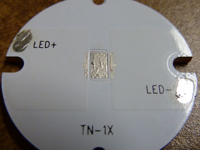
How do you know it's a direct thermal path copper MCPCB?
I mentioned in an earlier post, actually without certainty, I think it is because I get electrical continuity between the pad and the underside of the PCMCB with a DMM, so I'm assuming so -- pretty sure on PCMCB's without a direct thermal path you can't get continuity. Actually I was hoping AlexGT or anyone else knowledgable with the TN31 star would respond to confirm or not confirm. I was wondering maybe this was changed by ThruNite, not sure, because AlexGT definitely thought it was not a direct thermal path based on what he did. From his OP:
8 Replaced the stock XM-L U2 with a XM-L2 U2 1C emitter from illumination supply, I direct bonded it to the copper of the stock PCB by filing off the central pad’s dielectric layer with a dremel, do not put too much presure and over do it, stop once you see the copper.
In the photo I posted of the PCMCB, you can clearly see the raised areas of the positive and negative lan's, but where the thermal pad is, there's nothing.