Money sent Mr. N. ![]()
Thank you sir :-) And thank you for the tip about conductive laquer. I use thin wire though and solder it. I dont have any of that conductive laquer.
A pencil mark works fine for me. Super easy and cheap.
I have found the pencil traces seem to drift in their conductivity with humidity…being in Texas on the gulf coast…the air can sometimes be as soggy as a wet sock or quite dry (depending on the prevailing winds) sometimes my pencil leaded strobe timeout traces work faster other times it seems like it doesn’t work at all (just a little FYI in case things seem a bit squiffy)
Good call and info on the pencil trace jumper though…thanks
A very nice service Ledsmoke! Thanks for offering.
(for me, I reflow them myself, or more correct: nothing is happening at all at the moment until probably half august because of family holiday activities)
Thank you very much for the tip on the pencil mark! That will mean I can test ALL the various setups of each driver before shipping it! Without leaving unsightly solder on the pads :-) TY
And thank you for the kind words djozz. I must admit that the last batch of 12 was made by my wife Lisa. She has taken an interest in this and since she has been on sick leave for a long time while fighting a heavy depression, it is wonderful to see that interest and also see the joy it brings her when I test them and they work exactly as intended. You have no idea how that warms my heart :-)
Hi!
I had time to play with the driver and the led…
I tried 3 different, fully charged cells but did never exceed 3,6 Amps???
I tried one of my cells in the solarforce T3 and there it gave more than 5A.
the Led was placed with thermal paste on a copper CPU heatsink
I soldered the minus from the driver direkt to the dmm cable
with my microscope app I saw a “strange” bridge?
what is that?
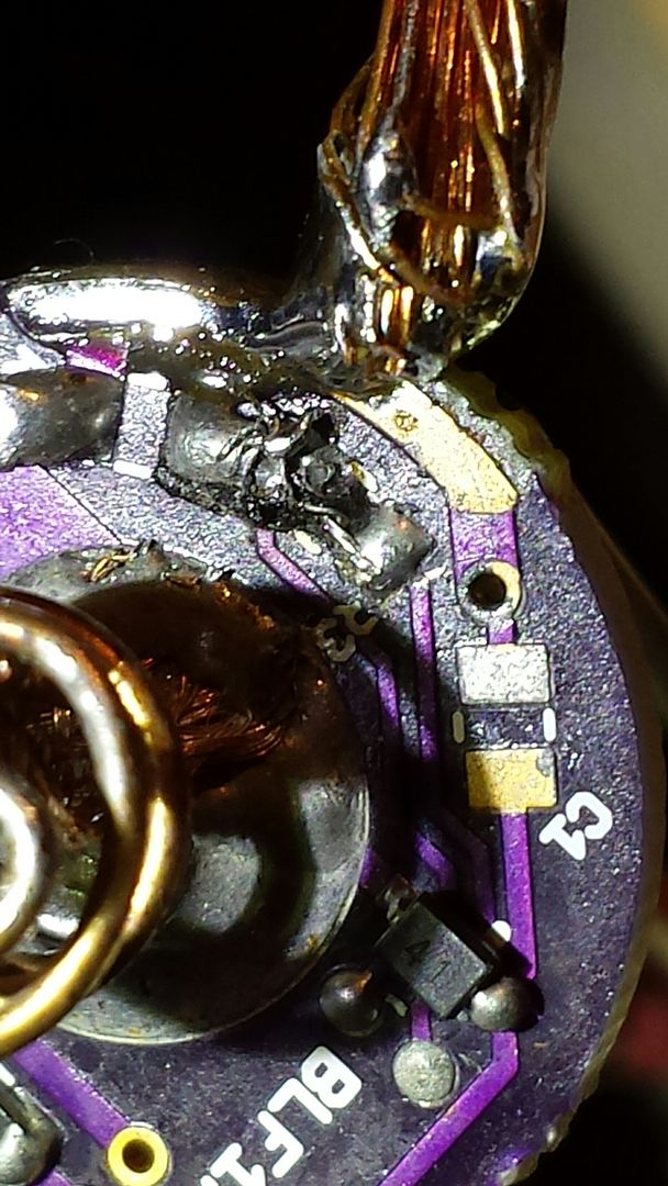
remainings of a wire you used?
what did I wrong?
Hi M4X
First off let me say that I am sorry about this. I cannot tell you why this is at all right now. I tested that driver here and saw 4+ amps. (My IMR batteries are old and my new batteries from fasttech are shipped via ground carrier so who knows when they will be here)
That bridge is a "fix" to the driver. It is just a short wire that is there because when these FET drivers were first developed. There used to be a resistor there.
But sometimes there would be erratic behavior and comfychair pursued that issue in this thread and dave_ suggested a fix that removed that resistor in post 50. But the driver still requires an electrical connection and that is just a jumper that connects the parts of the driver. I ordered these boards when I thought they were fully developed but alas new fixes has come up.
That said it looks terribly crummy that bridge when you magnify it like that. Yikes! :-(
Can I ask you this? How long are the test wires you are using and how thick are they? In my test setup I use the lenght of wires fitted to the driver (~11 cm) and another 8 cm of wires going from the screwed connection on the test bench to the emitter and I noticed that when installed in a flashlight the reading will be more than an amp higher. You could try installing the driver and test it there??
I will look into this tomorrow as it is late here and I need to get up tomorrow.
If the problem persists I will send you another driver no charge. Out of curiosity I might pay you to send the other one back so I can dissect it. That is if you are willing to do it.
I am sorry I could not be of more help right now.
Hey!
with the same setup i meassured the same battery the the T3 at 5A+
(wires are 2,5mm² / AWG13 - 15cm long)
the LED was connected using the presoldered wires.
i was abusing the Pill from my HD2010 yesterday night - give me (and my girls) some days to finish the build…
btw:
on the battery side, there is one cap which blocks the driver from being mounted with a retaining ring ![]()
any idea to overcome that issue? glueing and solderblobs for connection is the last thing i want to do
Oh! Sorry. I though the cell was tested inside another light (Solarforce T3)and not on the same setup. My bad.
That capacitor just needs to be between Batt + and ground so you can move it to anywhere that it does that.
I have sometimes filed some retainer rings a little bit to make the opening bigger to make them clear component on these and other drivers. Maybe that can do it here too? I am unfamiliar with the HD2010.
If you like I will test another driver tonight and have it mailed to you tomorrow.
I will make sure that the output is up there where it should be.
I am not sure when I have time to do further testing…
(wife and my Baby girl need time too ;))
no need to hurry - I trust you!
If the driver is broken you we will find a way to fix it.
or maybe its my fault and then it’s good for others not to make the same…
Of course. Family semi-first. Then lights... Ha ha :-)
I will wait a little bit and await report from you. I will make up my mind if I just send you one anyway. Then you can test side by side. And send back the one you do not like....
BTW. Solarforce T3... What light is that. I cannot remember how that looks. Or find any info on it on the web?
Ah! I should have figured that out myself... Doh!
Hmm... What battery are you using? Pana NCR18650B like in the review of that light?
Because with a single XM-L2 (instead of three XM-L in parallel) that may be the issue.
These drivers deliver only the highest amps with the hottest batteries.
For reference I have made a set of measurements tonight.
The same batteries were used throughout this test and they were not recharged in between.
First set is through a similar driver as the one you have. This test setup's wires includes
30 cm 2,5mm2 cable with alligator clips
12 cm 18 gauge silicone wire
A ~80mm solid copper shunt resistor of 1,5mm2 wire for measuring amperes
Another 12 cm of 18 gauge silicone wire that are mounted on the driver.
Panasonic NCR18650B. Battery is about 3 years old but otherwise working well as daily flashlight battery. Resting voltage 4,14V 3,5 A.
Unprotected Sanyo 2000 mAh laptop pull. Battery is about 4 years old and working well as daily flashlight battery. Resting voltage 4,14V 4,1 A
Sanyo IMR 1600 power pack pull. Battery is about 5 years old and working well as powersource in hot lights. Resting voltage 4,13V 4,5 A
Last set is true direct drive. THIS setup's wires includes
30 cm 2,5mm2 cable w. alligator clips
12 cm 18 gauge silicone wire
A ~80mm solid copper shunt resistor of 1,5mm2 wire for measuring amperes
Panasonic NCR18650B. Battery is about 3 years old but otherwise working well as daily flashlight battery. Resting voltage 4,12V 3,5 - 3,6 A. Meter shifting constantly.
Unprotected Sanyo 2000 mAh laptop pull. Battery is about 4 years old and working well as daily flashlight battery. Resting voltage 4,14V 4,2 A
Sanyo IMR 1600 power pack pull. Battery is about 5 years old and working well as powersource in hot lights. Resting voltage 4,12V 4,6 A
To me that indicates that if you are using Panasonic NCR18650B batteries the 3,5 A is probably what those batteries can deliver. It is what my similar batteries can deliver at least.
This is due to the high Vf requirement of the XM-L2 VS the 3 parallel XM-L in that solarstorm light where you tested the battery.
Furthermore a XM-L2 has a higher Vf requirement if mounted directly on a copper mcpcb like that Sinkpad you also got.
So:
parallel emitters -> higher amp reading
XM-L VS XM-L2 -> higher amp reading w. XM-L
Hot batteries like the Sony VTC5 or other IMR batteries -> higher amp reading
Unprotected batteries -> higher amp reading (this is due to the voltage drop across the protection circuit. Safety bites ;-) )
I am sorry if all this comes across as if I am trying to school you. Reading through this wall of text I just wrote I can see how that could be the case.
I am not though. Just trying to get to the bottom of this and pursuing a possible reason.
so 3 emitters can suck more amps from one battery than 1 does?
and thanks for your testing!
I am sure that’s a lesson not only for me…
I had time to play a bit…
1 cell 3,5 A
2 cells 3,7 A
but since I don’t have high Amp cells ATM I keep it as it is.
shipping back and forth is more money spent than the driver is worth.
Hi M4X.
Just FYI
I just got some Samsung 20R batteries in that are new and with those I hit about 6 amps on my test rig.
source / price? ![]()
Oooops. Sorry I did not get back to you sooner. I just saw this.
I got a local deal on a Dewalt battery pack from a foreclosed business locally. Brand new. Comes to about 6 Euro per cell.
i tried with one of my latest pulls
gave me 3,9 A
(3,6 with other unprotecteds i used above, 3,3 with protected pana NCR)