There are spare pins, but the standard MELD firmware doesn’t support putting voltage (or other functions) out on them. If you would like to create an entirely custom piece of firmware for your project, we can discuss that separately.
so what would a blank 18mm board and flashed MCU cost?
I can reflow drivers myself, and will piggyback the protection diode
the capacitor on the MCU is like 1uF?
In order to put a protection diode in there, you’d have to cut traces to separate the “dirty” side from the “clean” side. I haven’t checked it out, so I don’t know how many traces or which one(s) need to be cut to provide isolation.
@tterev3
I thought that if the voltage measurement code already exist it would be not a big deal to switch the output to another pin. But if it is to much work i will go with the normal FW.
You’ll need to get a bare bones board for $10 - I have to solder the microcontroller down in order to program it. The cap is 2.2uF
Unfortunately with a piece of code this complex, there’s no such thing as a simple change. I can’t support customization requests since they very quickly get out of hand with time investment, revision control, and bug creation and fixes.
I can flash MCUs myself if you provide the hex file
getting the MCU is no big deal for me, just need to make another acupuncture programming cable
The firmware isn’t open source
then I do not understand why you sell barebone boards?
a hex file and the Atmel studio project files are 2. different things, the ladder is open source
from a hex there is no way to change anything in the firmware as its not open source
But with a hex file, you could flash as many drivers as you want without the author’s permission or compensation.
How’s that? The firmware is the one thing I want to keep proprietary, and selling bare bones boards is the cheapest way to get it into other people’s hands without giving it away.
so the barebone board include a flashed MCU?
Yes, as described in the original post: bare bones option will consist of a PCB with microcontroller and capacitor
@tterev3
If it fits (and it is looking good) i want to use two momentary switches for mode switching and one clicky at the tailcap (can i use a forward clicky at the tailcap or do i need a revers clicky switch?).
The tailcap switch should be reverse clicky (and definitely not momentary)
Ok than i have to find a reverse clicky that i can fit in the tailcap to convert it to a lighted switch. The 2 momentary switches are in the head. At the moment it is only one but i checked if i have enough space to fit in two small ones and it should fit. Here is a link where you can see the light (Did you know this Host? - #15 by TheOnlyDocc)
Convoy M2 can be very perfect assembly by 18mm click board.
Do not need to do some modify.
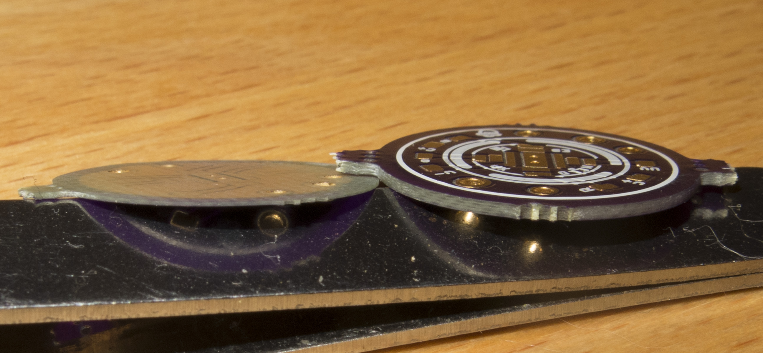
got my Oshpark boards yesterday
2Oz copper board sanded down from 0.9mm to 0.3mm
cutting out the XPL footprint with Dremel
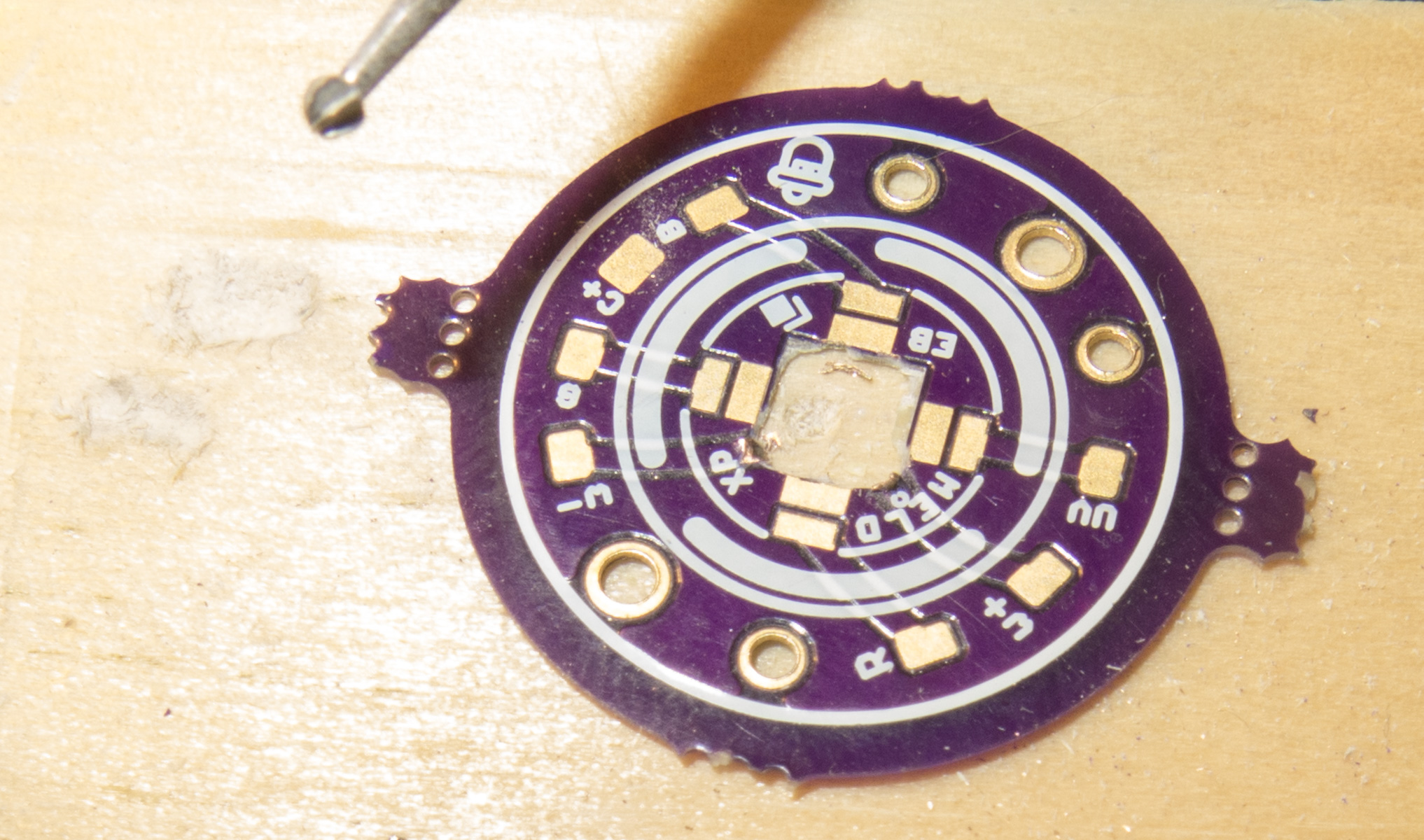
used a sharp knive to trim till the xXPL fits

Glued with Arctic silver 2 component adhesive
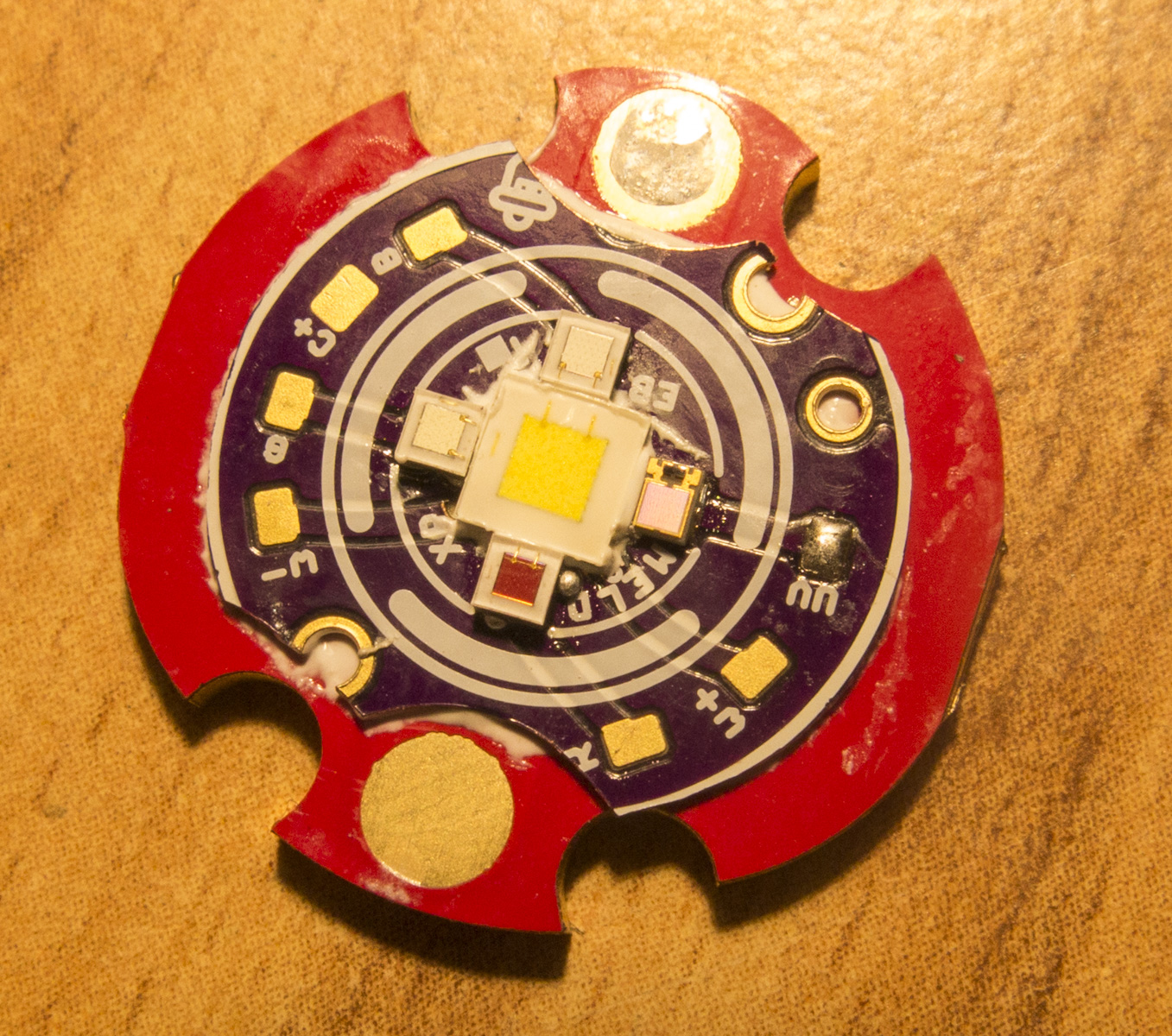
now waiting for the driver
I a newbie to flashlights BUT I would love to have a flashlight with this driver! Dimmable LED with RGB??
Could I replace the driver in my Nitecore HC30W with this one? How difficult would it be? Any video tutorials?
Or can I send it to you to “pop in”? ![]()