Thanks 
I did consider early on to drill through it like you in the original LZZ-06 mod.
But i am not sure i trust solder to not weaken (i have had that happen before) with all the twisting and pressing + running it hot i do when i use it with driverless modes.
And it seems like solder leave gunk on the cells tops and because these little powerful lights need a cell swap quite often (a couple of times a week for me), i don’t want to get toxic lead residue on my fingers and have to think about washing that off.
A bigger 18650 cell you can easily handle and place in the charger, but the small 10440’s i find i have to press on the cell top to get it correctly centered in the Xtar MC0.
But it may be possible to use solid copper and maybe hammer it in place to not have to use solder to fix it. But i don’t know if a solid wire would be less resistance than fitting a silicon wire than i can make oval to fit like in version 6.
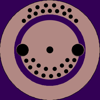
Another way i think it is possible to get a bit more amp (I know your post where about using stiff wires, but my aim to use a stiff wire where to get a thicker wire with lower resistance, and so far using a even thicker but more malleable wire seem to be a better solution) is by a bare max amp connector board with lots of vias for minimum resistance, like PD just did with the max amp switch board. Oshpark Projects post #1607
If you try out driverless modes on you LZZ-06 mod, please let me know how the connections hold up and if i am right on my concerns that it smudges of on the cell top.