The most challenging part of the build was removing 7135 chips from the driver board. I won’t need supernova brightness with this light. I also put different spring on the driver board, as my protected cells were a very tight fit with the original board.
As it’s your first build we’ll allow you some leeway but the general rule around here is “Pictures or it didn’t happen”. :bigsmile: so show us the beam shots and glamshots.
Congrats! Strong work now let’s see some pictures, please. Like Rufusbduck said, without pics it is just theoretical. Don’t worry about how your soldering looks, mine is worse. ![]()
Congrats on your 1 build, but
why would you want to decrease the time spent in this “job”?
Are you trying to mass produce flashlights so it is important to spend as little as possible time per one individual unit!
Or you do it because it is enjoyable and funn…
P.S. don’t worry i am just messing with you ![]()
You make a good point. ![]() It was very relaxing to do the builds
It was very relaxing to do the builds
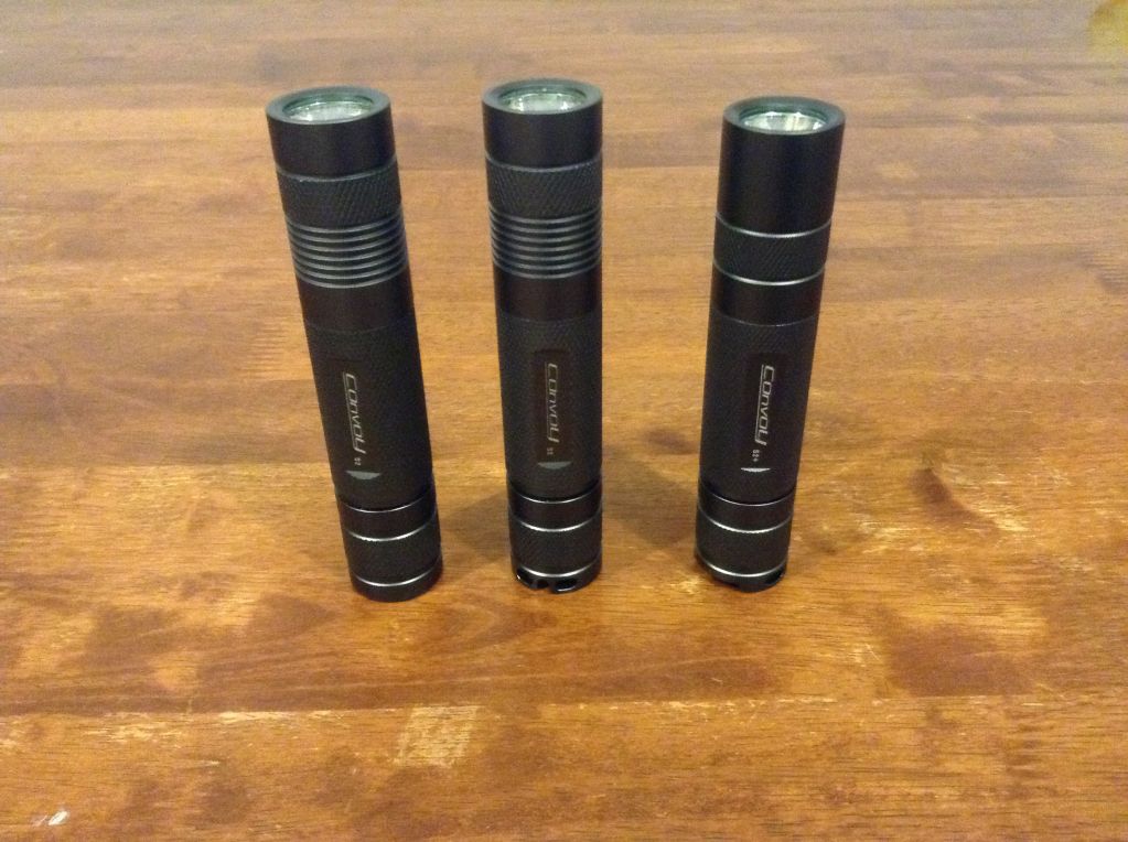
Here are some pictures. In each picture, the S2 on the left is the one that Richard built for me, with the XP-G2 R4 5A1 emitter. The S2 in the middle is the one I built, with the XM-L2 T6 3C emitter. The S2+ on the right came from Banggood, with the XM-L2 T6 4C emitter.
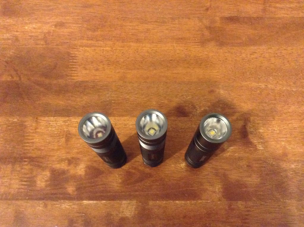
Here is a shot of the reflectors and emitters. Notice how the S2+ has a shallower reflector. It also has a much larger pill.
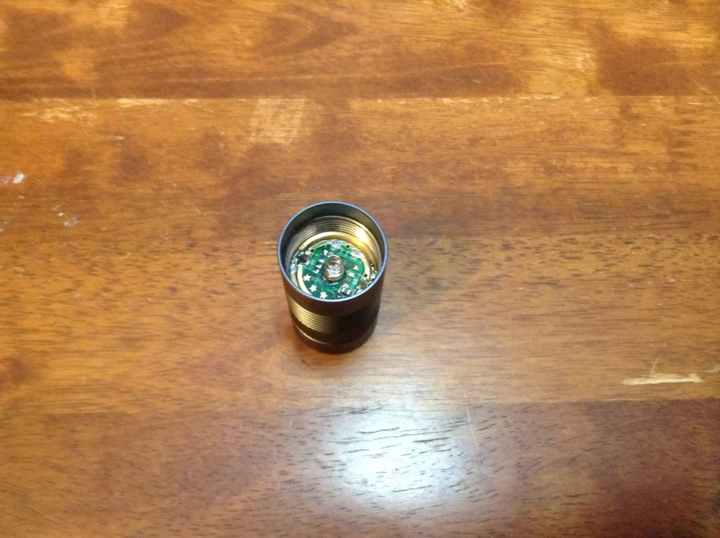
Here is a shot inside the head of the one I built. Before I fitted the emitter or driver, I used my old Weller D550 soldering gun to tin a couple of places on the pill. This seemed to make it easier to solder the driver to the pill with my regular soldering iron. You can see where I removed the 7135 chips. It wasn’t the cleanest of removals. I also changed the spring on the driver. The one that came on the driver was very stiff, and made my protected 18650s barely fit. In fact, it dented in the button top on a Tenergy battery. The new spring was scavenged from an old 3XAAA flashlight that quit working.
Here is my first attempt at a beamshot. I only have my iPad on hand, so the picture quality isn’t the best. The one on the left is the XP-G2 R4 5A1, built by Richard. The middle is the XM-L2 T6 3C I built today. The right is the S2+ from Banggood, with the XM-L2 T6 4C.
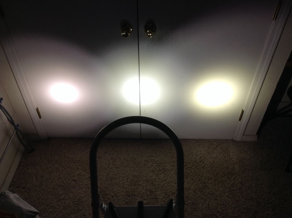
The beamshot doesn’t do the beams justice. The one on the right has a larger and less distinct hotspot than it appears. The colors also look different in real life. The one on the left has a very slight hint of rose. The one on the right is slightly creamy. The new one in the middle is closest to neutral white.
Yeah, they showed up…very cool!
What, who left that capacitor over there, that is not acceptable job ![]()
I didn’t realize I should remove the capacitor. I guess that shows the newbie in me. Does it make a difference if it is there or not?
no no…that’s the Nanjg driver, and/or star 4 to ground for the JohnnyC’s off-time memory firmware ![]()
not remove completely but you can relocate it to the other side of the driver…
are you sure, doesn’t look like that !!!
My driver has the NLITE firmware. I did ground star 4, as I don’t want mode memory on this light. This light will be used when I get up before dawn. I want it to always turn on in low mode, so I don’t blind myself.
I just looked at the driver that Richard put in my first S2. He removed four 7135 chips when he built that original light, and left the capacitor in the original place.
I don’t think I’ll try to move the capacitor to the other side. I may be able to remove it, but I’m not as confident in my ability to resolder it on the other side. I haven’t done a lot of surface mount soldering with such tiny components.
Here is the driver I put in this light:
I ordered it with the standard NLITE firmware.
Ah, you see, it’s not off-time memory version ![]()
Soldering smd components is easier than desoldering them ![]()
Thanks for letting me know. I’m learning a lot tonight. ![]()
Here is where you can move that capacitor:

courtesy of comfychair ![]()
Thanks.
I have two more builds coming soon. I think I’ll try moving the capacitor on those builds, as it will clean up the appearance of the driver board a bit. Hopefully, my chip removal will leave better looking results next time.
If you ordered that, where are the 4 7135 (380mA) chips at? or did you have them remove them?
I removed the chips myself. I mentioned my removing the chips in reply #7 above. Removing the chips was the most challenging part of this project.
Here is a picture of the 7135 chips I removed:
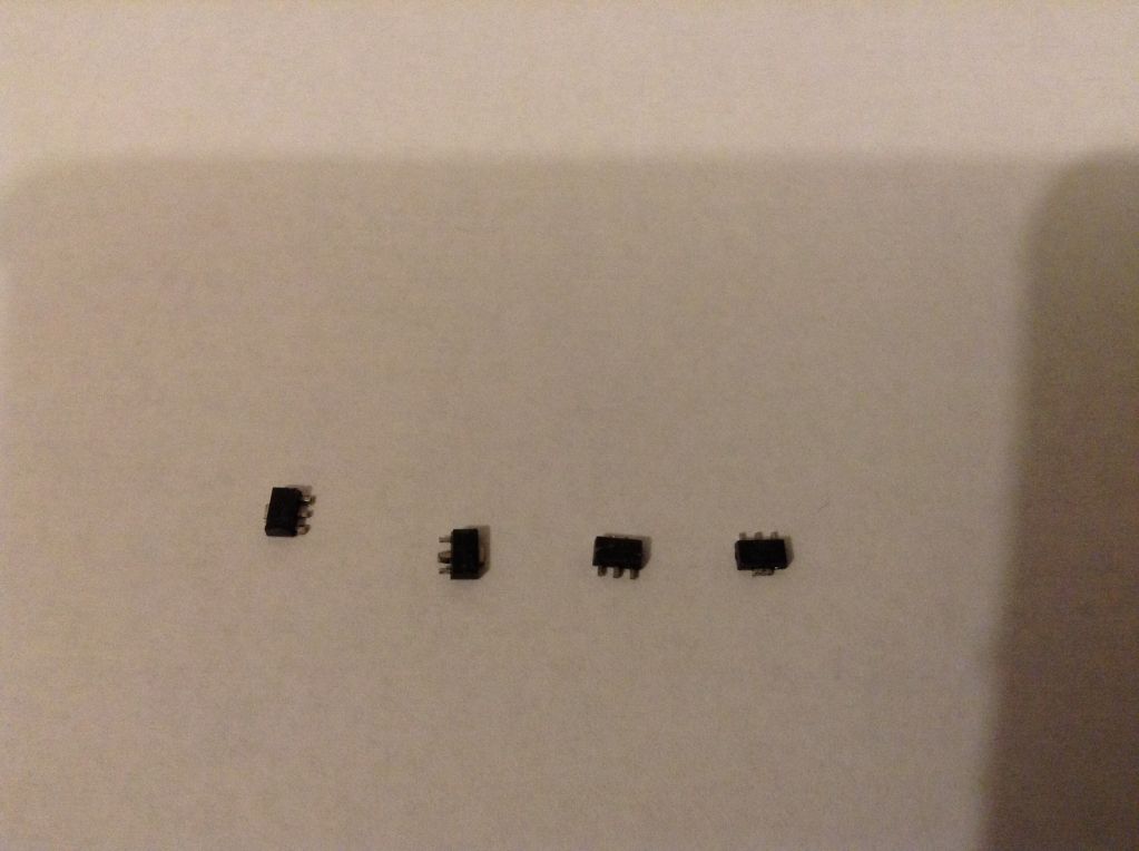
I will store them in a small Ziploc bag in case I want to use them sometime in the future.
I had considered having Richard remove the chips, but I figured the driver would ship faster if he didn’t have to remove the chips before shipping the order.