KD 8x7135 driver - Direct drive?

Hey guys,

Has anyone used this driver?

http://www.kaidomain.com/Product/Details.S020074

Just got 5 of them, and every single one is pulling over 5 amps, basically direct drive.

Looking at the pin out diagram, all I have done is put the postive to where they say, and the negative likewise, however, if you look at the positive trace on the led size, it actually has a trace on the opposite side direct from the spring?

Or am I just crazy?

Chris

7135 drivers have the LED+ always connected straight to BAT+ at all times, the current regulation happens on the negative side, between LED- and GND.

Do the modes work correctly? If you have the LED- shorted to ground somewhere it will completely bypass the driver, and it'll be single mode only.

No modes at all.

I tested it out of the host, so theres no way there can be a short, however, I have quite often deliberately shorted the led directly to the pill and never had a problem with modes or anything before.

Im out of ideas!

Chris

nan1

Battery positive is where the spring is. Ground, (as in body or battery ground), goes to the outer ring.

nan2

LED positive and LED negative go to the pads shown here.

As comfychair said, the regulation is through the negative side.

If you have soldered LED’s negative to ground (not LED ground but battery ground), yes you have a direct drive driver without modes or other electronic applications like battery low or over heat protection.

hmmmmmmm.

I have used 105c’s for ages but just tried these KD drivers which are quite a bit different.

Maybe the batch ive got is crap, I dunno, but its definitely not wired to ground, plus its out of the host and I can see all the solder joints too.

One for the morning i think!

Chris

Old-Lumens, OP has the KD 8x7135 v2, your pictures show the Nanjg105/Qlite, this might lead to some confusion.

The KD driver has a different layout. I like him as a great alternative, for his different mode options and being without PWM-whine. You find more about it in this thread.

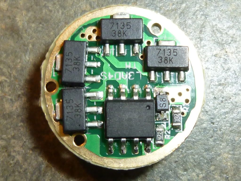
As you have single mode only, odds are you soldered LED- to GND. In the pic you see LED- as a solder pad on the upper left, it’s the smaller one compared to LED+.
LED- and GND (the outer copper ring) are not to be connected. They are very close, so this can happen easily.

From the LED- pad on the star, to the ground ring on the driver (or to the pill, if the driver's already soldered in), shows what when checked with an ohmmeter?

If you have a DMM take an unused one of the 5 and check if LED- is connected with ground out of the box.
HQ