In lights were it’s needed, a standoff ground ring can be used that sits above the components. I’ve had to do that on 19mm drivers w/no ground ring at all.
Think of it as good practice Dale
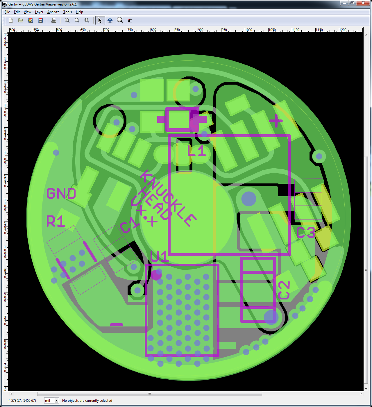
I am pretty tired right now, so I could be wrong. I don’t think it is workable with the current layout, please look at the overlay. You think having the output and GND pressing against each other is a bad idea. You might be right :-). I will think about the layout possibilities more.
Yes, the positive pad will be moved slightly within that kind of triangular copper pour it sits on. I will try to get the same clearance between the pad and GND as well as the pad and the diode next to it.
There are days I build several lights in a few hours. Days I build none at all. And some days I can kill multiple drivers without breaking a sweat…
I might stack 40 7135 chips with amazing ease, and then spend 25 minutes on one stinking leg that won’t cooperate!
I’ve reground a solder iron tip to easy to use dimensions (about .75mm), and used it for months, only to be told you can’t do that. (accidentally left it on once and fried it, probably need to regrind it, but then, you can’t do that…) And I bought flux on the advise of some well respected folks and started killing boards when I used it.
I solder with no magnifying glass, no helping hands, no added flux and usually the 1.5mm slanted tip that came with the Hakko 888. Even if it’s one of those little resistors that looks like a flea and hops like a flea when you grab it slightly wrong with the tweezers.
With my memory, it’s all practice. Will always be practice, even though I’ve built some 80-100 lights. (55 of which are my own) And when the boards get here from OSHPark, I get to practice some more! But will most likely have built at least 3 more lights before the Knuckleheads get here Friday. ![]() Built 4 on Monday, one more on Tuesday, with 4 on the way and a fifth I’m waiting on for an ultimate build. That one scares me! And the 25mm bullet waiting in the corner.
Built 4 on Monday, one more on Tuesday, with 4 on the way and a fifth I’m waiting on for an ultimate build. That one scares me! And the 25mm bullet waiting in the corner.
Now, where was I? :~
I bow to you most excellent sir. I can’t do squat without both hands, a good strong light, and a magnifying glass. Not to mention a small tip and lots of rosin flux. I frequently pretin and will probably screw this up anyway so I know I certainly need (but don’t necessarily want) the practice.
Even though I do this all the time, it’s still practice every day. I forget what I did right before. And how I solved a problem, and have to come up with answers to the same problems as though it was the first time, every time. Maybe not quite as bad as the chick in “50 First Dates” but along those lines. lol
I’m amazed at those than can design these boards, troubleshoot all the angles and know pretty much in advance what’s gonna play nice with what and who’s gonna be the troublemaker. That’s crazy good, and I watch and I study the boards and then shake my head (figuratively, not literally…one head shake no is an immediate intense headache) and sit back and watch some more.
I guess it could be said that I’m just a Chucklehead with a Knucklehead… hey Steve! Grab that hammer and hit this right here while I hold it down!
Has anyone hollered at this guy for possible input? (stumbled across this looking for the mouseovers of the nanjg 105c board w/ components then showing traces)
I did some testing this weekend, although it was too late at night to take great documentation of everything.
Observations:
- The buck IC is stable and seems like it will last well at 1.5A-2A maximum. After that it gets extremely hot. I tested using various resistors + trimpots to tweak the current.
- At 4A it gets hot insanely fast and tends to burn up pretty fast, spitting little pieces at your face.
- I tried a larger inductor (coilcraft, can't remember exact specs) and it seemed to help a little bit, but certainly not enough to get you up to 4A (still burned up.)
- You can stack two of the buck ICs together; it works and will light up etc., but it doesn't give you any extra capability or reduced heat. My guess is that one of the buck ICs is still doing almost all of the work.
- I didn't have good luck trying to parallel two of these boards together. I tried several times etc. and I kept on blowing LEDs. I thought that maybe it was just spiking voltage at startup, so I added an empty 2200uF capacitor in parallel and it still blew the LED.
Casualties:
- 5 Buck ICs
- 4 XM-Ls
- A Few Hours
I was thinking it was all my fault. ![]()
Got the heat sink done for the V1 board. It has an awg12 solid wire brazed to it with a matching hole in one pcb and notches for wires to connect the signal vias. All the ground vias besides the #12 wire will also get fine wire soldered through to the sink. I’ll use 2 pcb’s with the copper in between.
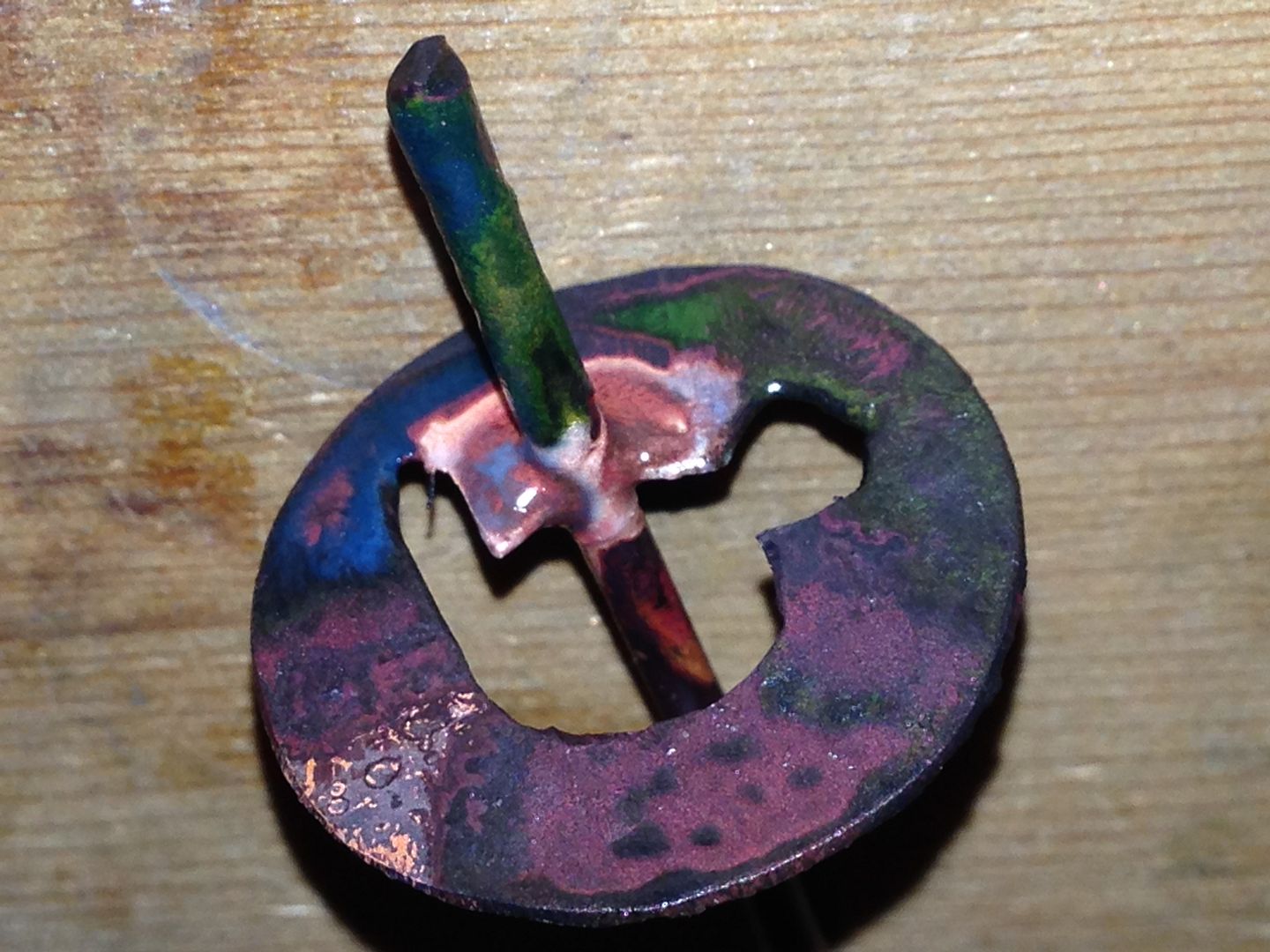
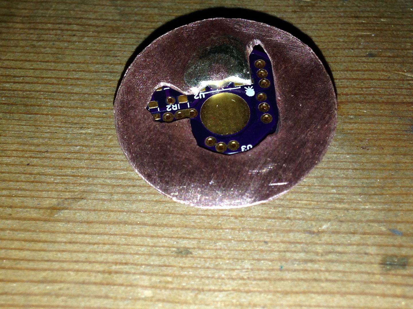
Once it’s assembled I’ll fill the void between the copper and the boards to make it solid.
Whoah…some interesting copper work there
Damn…sucks that the current is only good for 1A - 2A if we can figure out why it won’t go higher…man it will be sweet
What rating inductor and capacitor are on the output of the LED2001?
Is there a schematic…been digging for one, can’t find it
I ran the eDesignSuite, it shows the dimming only going up to 20%

I’m not second guessing or whatnot…just don’t understand it all [no engineer]…the “dimming” function when I clicked the button showed 1–20 like it couldn’t actually reduce to 0% output
Even with this design it is running at 1.9watts dissipated…and that is right at it’s max
Thanks for doing all this work RMM. That’s important information for us. Can you tell me the specifications of the inductor you tried? That could be important.
It’s a “monolithic step-down step-down current source with synchronous rectification” - that means that inside this tiny package are:
- a pretty fancy buck controller
- an FET
- another FET
Considering that for >2A of current with a non-sync buck we’d normally use an FET package at least as big as this device along with a diode of similar size…
Actually it’s not. You are seeing 1.28W, which is not right at the max. Maximum dissipation is for the IC, not all the support components. At least I’m pretty confident that that’s the case. I never took that into account in my own calculations because I did not know the breakdown. I assumed the lion’s share of the losses were in the IC. The calculator shows that while this is the case, there are enough losses elsewhere to put us back inside the spec’ed envelope.
Also, you are misunderstanding the dimming thing. That button pulls up the “LED Current Ripple” dialog, which let’s you set allowable current ripple. It is not a dialog to simulate dimming, it is there to help simulate and aid component selection.
I never assembled any of the boards I got, either the Knucklehead v3 or the tweaked version I ordered with better heatsinking for the LED2001. Improved heatsinking is a good thing, but it won’t fix what RMM has described - that is not a heatsinking problem. EDIT: or at least it doesn’t sound like one to me.
Coilcraft XAL6060-472ME
4.7uH inductance, 13.1 mOhms typ., Isat 10.5A
vs.
3.3uH inductance, 19.9 mOhms typ., Isat 12.2A
I am not of the belief that this IC will ever put out 4A reliably in our applications. We need to move on and keep looking.
Thanks again for the info. I agree about moving on. I was discouraged and never assembled the boards because it didn’t look like this thing was going to do what I/we wanted. I felt bad about it, but now you’ve done the testing for me.
EDIT:
It’s worth noting that when I ran the simulator it did not suggest an inductor with such a high current as what was shown in the application circuit from the datasheet. The simulator suggested an inductor with an Irms of 4.5A and an Isat of 5.4A, way lower than what’s shown in the application circuit.
WarHawk-AVG: I think you want to be using an Rd of closer to 1 Ohm rather than 6 Ohms, but I’m not certain. Did you guess that value or did it come from somewhere?
All I know is that the best buck drivers I know of by George at Taskled have boards with thermal vias and require additional heat sinking above and beyond what is provided by the ground plane of the board. Until someone has assembled one using the new improved board with an additional attached heat sink I’m going to assume that it’s no different than trying to run an XML on FR4 vs a Noctogon. George actually recommends sinking both sides of the chip at high current and I don’t expect to need less with more current on a smaller board. I’m channeling Winston Churchill here. :face_with_monocle:
That 1/4” thick triangle of copper I attached to the back of the regulator had it working fine at what, 3.6A? I have used the MT-G2 that I was testing with, but it was working fine when I pulled it from the circuit. I have thought about using a pair of XM-L’s on it and running it some more. Could I run 3 series XM-L’s? From 2 18650’s? Or would 3 and 3 work best? Might have to play with it and see if I can kill it. ![]()
3 & 3. 3 emitters and 2 li-ion won’t work.
To maximize stress, keep the output low and the input high. To minimize stress, make both high.
The reason why I subscribed to this thread was to see if this driver was capable of doing ~1.5a to an xm-l/mt-g from a 9 or 12v source. Do you think the chip can handle it, or would it blow?
That diagram from above came from the manufacturers online circuit builder…I punched in the Vf, current, and resistance…it calculated the rest