The FET driver in my M8 is driving the MT-G2 at 12A from 2 C4’s, seems like the cells as well as the emitter are running a pretty good race. Not enough? The single 20R in my Bucket C8 is pushing an SST-90 at 16A. Race anyone?
But for how long...? The issue is, it's getting dimmer as soon as you switch it on. A buck driver where the input voltage is NEVER lower than the LED's Vf will have a constant output from the time you switch it on until it shuts itself off due to low voltage protection.
With nearly 60 lights to play with, I’ve yet to see one maintain a certain level of performance in my lightbox very long at a time. Factory or otherwise.
Besides, isn’t that pretty easy to do? Just run almost any LED at the factory specced 350mAh, it’ll run almost forever minus lunchtime. ![]()
Nobody is saying that a buck driver is a cure all. You’ll still have other issues, this is just eliminating ONE problem. The way we tune direct drive lights with static resistance or PWM is lame and prevents both maximum performance and good maintained performance. You’ll rarely hit the maximum current on the bulls eye that way, and you’ll definitely never maintain it. Direct drive also only works well on emitters with a relatively high Vf - it won’t work on LEDs that need a Vf like 3.0v or 3.4v, they’ll just poof. It also won’t work on LEDs with a Vf that’s too high - a 4.0v Vf isn’t something we could feed off of a single li-ion if it showed up! The low voltage LEDs exist now, look at XP-series and others - especially colored emitters.
A linear driver is the simplest way to regulate for those LEDs, but a buck driver is the most efficient and the gives off the least heat.
I know from lightbox results you’ve posted in the past that you have lights which tank immediately after turn on as well as those which can (mostly) maintain for 30+ seconds. So I think you’re just yanking our chain on the “maintain a certain level of performance in my lightbox very long at a time”. Obviously some lights have advantages over others in the maintenance department.
Being able to produce big results with batteries that haven’t just been topped off (half empty 20R’s for example) isn’t something you can do with direct drive. With a buck driver you can still do it. Pick up a cold light with half-dead cells in it and enjoy the same turn-on lumens as you’d have gotten with fresh cells. Another, related advantage is that while you probably lose some efficiency with really high input voltages, you also reduce pre-driver resistance losses the higher you go. As you increase the input voltage to a buck circuit the input current will drop proportionally - at some point your voltage sag should be reduced enough to think about skipping spring mods and stuff.
Oops! Sorry, I thought it was Natl. Jerk Comfy’s chain day! ![]()
Yeah, there are times when such a light is highly desirable and will be used hands down over the hot rods that just can’t hold up. I’m almost afraid to find the “perfect light” as then I’d have to sell off my collection, no longer able to explain to the wife that each has it’s place…
I am very interested though in a good constant regulated driver. A decent output, not necessarily high but decent, to use for hours at a time when necessary and get the utmost from the excellent cells such as Panasonic’s PF. I’m still new enough that the 300 mph 1/4 miler is a blast, but old enough here to see the sheer value in longer run times with much more efficiency across the board. Hoping to see some of that with the 3 Knucklehead drivers I’ve got on the way… Looking to run an XM-L2 around 4A for an hour from 2 cells on High.
Next is to figure out what host to use…looking into a lathe, might have to make said host myself. ![]()
Sorry the analogy I used was to convey that the FET was awesome for impressive but shorter runs and the Buck was impressive for much longer runs. Not that one was better than the other but more apt to suit certain applications than the other. I hope to someday build multiple copies of each. But let’s not get bogged down with a Tastes great verses Less filling debate ![]() Let’s get back to how to make this driver.
Let’s get back to how to make this driver.
No need to apologize scottyhazzard. Your post was a good one and it prompted a good discussion. I certainly wasn't calling you out. You put a pretty darn good analogy out there. I dare say I couldn't have thought of one as good.
To me, the discussion helps point out that there are very few reliable high current buck drivers out there. And no, average joe DIY options. Mattaus' most awesome and unselfish contributions are moving us in that direction. Which is so cool.
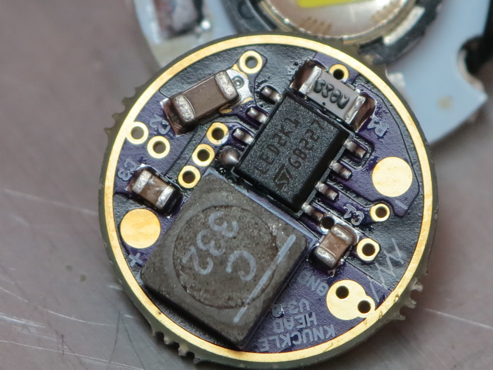
I’ve got all the parts, have one side populated and came in here to determine orientation of the Coilcraft inductor. I see you’ve got the line on the left, so that’s what I’ll do…
The parts list got me ATiny13 MCU’s which aren’t compatible with my .hex files, so I flashed an ATiny13A and am about to put that on there. Hope there’s not enough difference between those 2 to cause issues!
Wish me luck!
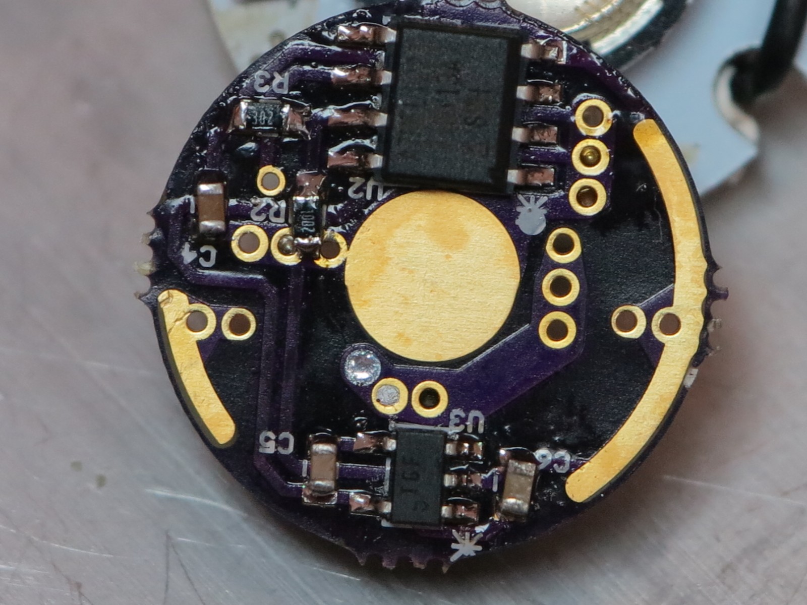
Hand soldered side…
Reflowed side…
Would like some confirmation before I attempt to power it up, but patience is not one of my stronger virtues so we’ll see how that goes…
Good luck Dale. Fingers crossed.
I have confirmed that all the components are on in correct orientation (mostly) The picture provided by Matt at the beginning of this thread shows the inductor in place with the line to the left, so that’s what I did with this one. The 8HSOP at U1 is correct, verified with it’s datasheet. The ATiny13A is correct. Everything is soldered clean.
The LED I’m testing will flash, but not stay on. I’m using 2 Sanyo UR18650FJ with an XM-L2 on a Noctigon and clamped to a 3”x3”x3” cube of 6061. LED leads are from the + and - as marked on the board. The negative or black lead is from the - on the board, not the gnd that Matt is using in his picture. I figured he’s not using pwm to control levels in that pic, am I figuring that incorrectly? At any rate, I can get an initial flash that isn’t repeatable unless some time has gone by. After a few minutes, it will flash upon connection then do nothing upon subsequent connections until, once again, some time is allowed to pass.
The Coilcraft pdf data sheet doesn’t show me what the orientation is. I’m supposed to know what that white line on top of the “C” means and therefore where it goes. Matt’s explanation as to why this driver is called “Knucklehead” shows clearly that the correct orientation is with the white line beside the pad marked GND.
So I must have something else out of place some way. I used a toothpick to put almost microscopic amounts of Kester solder paste on every pad, then very carefully and tediously placed each component with needle sharp tweezers and a toothpick to ensure the part stayed lined up as I released with the tweezers. I don’t know now where to look.
That flash and some time before another makes me think a cap is shorting out or something. So I guess I’ll start removing those and double checking one at a time until I can get it to work. Barring that, I’ll wait for some input from Matt or anyone else in the know as to where to look for the problem. After that I’ll nominate it for a blind date with the 16lb sledge.
Good news is it works perfectly, bad news is that the moon mode I have programmed doesn’t work, acting like a blank or off mode. Hilarious news is that I had to connect the electronic switch to make it function. Knucklehead is a very apt description for this one. And it’s builder. ![]()
Dale, now you owe us some numbers. How low can the output go, in amps/lumens (not PWM value.) What kind of current are you seeing to the LED?
I think Matt mentioned that it might not go super low but I could be wrong. Maybe play with that value and see where it starts to be reliable?
Nice work dale :)
The orientation of the inductor doesn't actually matter. Just as long as you don't do what I did and bridge the inductor pads lol.
In regards to the low mode - the PWM frequency will effect how low you can go. What frequency do you have the MCU running at? I sort of explained it a few posts ago but when I get home I'll have a look again. I'm still waiting on all my parts :(
WOW…beautiful build!
FYI you can reflow both sides, just flip it over, put the solder paste and components down…then use the reflow heat gun and it will reflow, the PCB prevents too much heat from going thru and desoldering the other side…plus surface tension holds the components on
First attempt there was no moon, it was set too low. Second attempt gives me 7 levels, low isn’t really all that low, but then the spring (OEM from Crelant) softened and everything got out of whack and I’m still trying to get it working again. Not a board problem, a mount issue.
Taking D to McD’s for a break, will hit it again later.
I got 1.86A at the tail initially, from a pair of Sanyo UR18650FJ’s that arent fully charged. Something like 1480 lumens. Back later, Ciao!
1.86A at the tail equates to what at the LED? I've never been any good at working that out. It should be close to 4A. It's specced to 4A, but there will always be losses that reduce the output.
- Matt
I’ve managed to kill the electronic switch, which was about half of the whole point to using this driver to keep the light working like it was designed to work. This side switch doesn’t have any notches or any other way to get a hold of the SS bezel/insert that presses the rubber boot into the head. It wouldn’t budge. So with no way to grab it I assumed it was press fit. Tried to knock it out. And broke the pcb the electronic switch was on. This was necessary as the tiny wires soldered to the pcb broke off and there was no way to access the pcb inside the host to reattach them.
At any rate, I will now be making a plug to seal the side switch up and rely on the tail clicky to run this driver. Aggravating as green snot.