I think when WarHawk-AVG made that comment he simply did not realize that you aren’t powering the MCU the way it’s done on a nanjg 105c (directly from the battery).
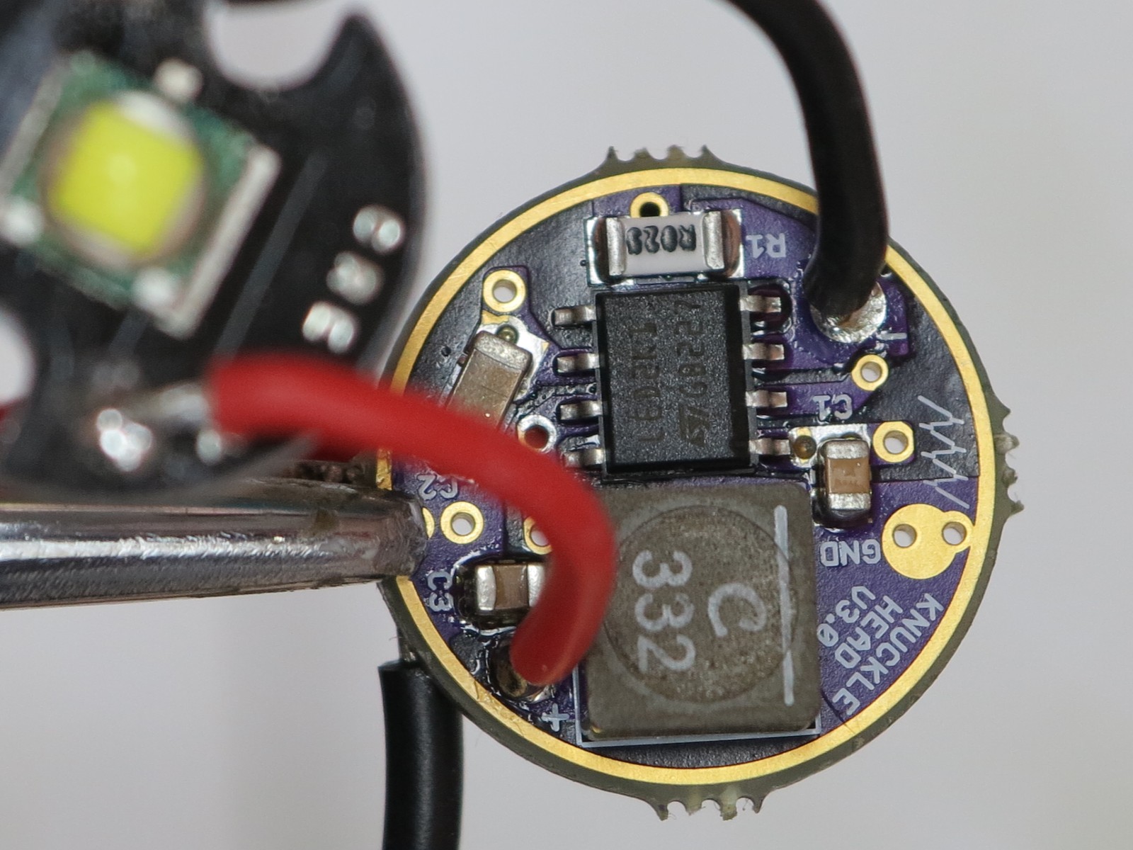
You solder the appropriate pin to ground. You just solder pin 5 to ground. If you hold the driver with the MCU side up and the MCU edge of the PCB pointed towards you, Pin 4 (GND) is on the bottom left and Pin 5 (aka Star 2) is on the bottom right. The skinny trace between pin 5 and 6 is also GND, so all you have to do is carefully scrape the purple resist off of the trace and solder pin 5 to it. If you don’t want to do that you can solder a jumper wire across the chip from pin 4 to pin 5. While we’re on the topic, pin 3 (the pin right next to GND) is “Star 3”.
If I have read the thread correct, all we need for code is to have modes and low voltage detection? If so, I might be able to learn how to program one of these in a day and coble a few peoples codes together.
Good reply. The most important thing to take from this is as that for all intent and purpose, the MCU on this driver is setup IDENTICALLY to the MCU on any NANJG driver. The only difference is that it has a regulated voltage supply powering the MCU, and that the LED driver it's controlling can't handle as high a PWM value as AMC chips can. Other than that, treat the MCU on the Knucklehead like you would on any "Star" driver.
You don't even need low voltage detection really. If your primary concern is to prevent damaging your batteries, then use protected cells. If you want to perform a "battery stretch" sort of function, then you'd need voltage detection so that you can automate the behavior of the light when the voltage drops to a certain level. Horses for courses.
Sorry. My "weird sh*t post" would not post what I was trying to post in the post after it (#162). No matter what I did, it would only add my last line. I gave up on it and started a new one, and it worked fine. WHo knows what I did wrong lol. And now it's gone all together. This is what I get for posting using two different machines at the same time. Don't ask haha.
We have modes and low voltage detection, but things aren’t perfect yet. What we need to experiment with is PWMfrequency (and once we’ve done that, potentially adjust some component values for best performance) and determine what freq to run as well as how the driver responds to varying 8-bitPWMlevels.
The ADC is 10-bit, so there’s enough room to measure 0-18v voltage with a resolution of approximately 0.02v. Matthaus mentioned that someone could write a “universal” firmware. The way automatic cell counts normally work is that we determine cell count based on voltage. Since we use a wide range of cell chemistries this could be an issue with such a wide input voltage range
2.5v – ~4.35v is 1s
5v – 8.7v is 2s 7.5v – 13.05v is 3s (adjust the lower bound up to 8.9v to accommodate cell detection. over discharged 3s setups will end up detected as 2s and LVP will fail) 10v - 17.4v is 4s (I think at this point there is no good way to count partially discharged cells!)
In other words we can easily measure 0v through 18v, we just can't figure out whether that charge level that measurement indicates. 16.8-17.4v obviously indicates a fully charged 4s pack, but 12v could indicate a flat 4s pack or a fresh 3s pack. You could either have a 2-bit code (2 stars) to pick which of 4 ranges you wanted the MCU to use or you could auto-detect 1-3s and have a single star to switch it over to 4s.
EDIT: what I meant above is that we can easily measure 0-18v in hardware without changes to the circuit beyond setting up the initial voltage divider for 18v. The issue remains that once we know what voltage the battery pack is, we still can't guess the cell count accurately in the software. Without that knowledge the MCU doesn't know if the pack is at a healthy voltage or not.
[quote=Mattaus]
You don't even need low voltage detection really. If your primary concern is to prevent damaging your batteries, then use protected cells. If you want to perform a "battery stretch" sort of function, then you'd need voltage detection so that you can automate the behavior of the light when the voltage drops to a certain level. Horses for courses.
[/quote]
I don't think I agree with this, really. Many users here (including me) have cells with crap protection circuits. MOST users here, in fact. HKJ has demonstrated bad performance for lots of protection circuits I think, including some on nicer brands. Protection in the driver is what I depend on.
aside: I was seeing some posting/quoting issues myself for a minute there
I cant add anything at all positive here but read every post here with interest. Maybe its the weird shit I'm on. Matt what are you on? I know what DBC and RBD are on but it had a inverse effect on what I was on. Maybe yours will be better?
Yeah, by universal I didn't mean plug and play. I meant code with detection incorporated for all four scenarios, and you had to manually pick which one it used. You certainly could not use 1 driver with one firmware for all 4 scenarios and expect consistent cell count performance. Not in the drivers current guise at least.
Fair enough on the protection circuits. I don't know why I assumed they were good. Every light I've ever built has has LVP included, but that's because I switch between protected and un-protected cells fairly regularly.
I think it would be better to purpose build the knuckle head for each use, figure the correct volt detect resistor divider for each series cell count 2x-3x-4x, then build it that way (the code for detection wouldn’t change for the firmware, just the hardware build)
Different strokes I guess. Here’s my rational though, see what you think. It makes sense to handle it in firmware, even if we must explicitly define cell count instead of auto-detecting. You have to flash whenever you build one of these things, so you can always change the code as needed. You don’t always have the parts for a voltage divider.
Sorry, Dale I’m late to catch up to all the great teamwork and progress you have made after so many set backs and wrong turns. Congratulations! Awesome work and an excellent demonstration that patience and perseverance pay. Made me think of Dylan Thomas…
Do not go gentle into that good night,
Old age should burn and rave at close of day;
Rage, rage against the dying of the light.
Below is a 20mm version I had made up for a project I'm doing for someone. It's a mix between V1 and V3. I had a brass contact machined so that I could use a full sized spring for the BATT+ contact. The contact in the picture below has not been soldered on yet because I need to finalize some firmware for the MCU, which is why R2 and R3 are also missing.
Why mix v1 and v2? To accommodate the through holes? Or just because that’s how it turned out
Yesterday I ordered everything to possibly build the buck side of the circuit cheaply, as mentioned. Now I want to build the other stuff cheaply, so I’m shopping around. I just ordered 5x of the expensive LT1761ES5-3.3 regulator from a USA seller on eBay for $4.99 total. There’s a seller in China with a slightly lower price – this may interest forum dwellers who live outside the US.
For anyone planning on building a lot using an ATtinyXXv part (such as ATtiny13v) there’s a guy on eBay dumping the 2.5v version at under 14 cents each. DO NOTPURCHASE these unless you understand the implications of running your MCU at such a low voltage. There could be other reasons not to do it too, such as I didn’t check the signal voltages for the PWM input on the LED2001 chip. I was tempted to try these but I want to look at using the tightly regulated 3.3v as the reference voltage for the battery monitoring and it would be harder to share my results if I was using 2.5v regulators.
I see that a bypass cap is recommended on the input to the LT1761, and a cap is required the output. The 0.01μF reference bypass cap improves the quality of the output and increases the value of the recommended output cap. It seems to me that the power circuit is probably good enough with 1μF on both input and output and no reference bypass. I'm not really sure that the input cap is needed either, but the datasheet says that it's advisable in a battery powered circuit. In our case we are running a <10mA load from a high capacity battery, so I'm just not sure we need to care about "In general, the output impedance of a battery rises with frequency, so it is advisable to include a bypass capacitor in battery-powered circuits." But I don't know.
That's all speculation and not recommendation on my part. I don't want to play armchair general too much with Mattaus's hard work. It's an expensive driver to build though, and if we can get the cost down without too many compromises it'll make all of us happy I think!
I have 10 more inductors on the way, along with a new order from DigiKey and OshPark. The success of the one board is a driving force that makes me want to do it some more! And so the addiction continues…
With 50+ lights on hand, one might wonder just why I’d want to order dozens of driver boards and the components to fill them. Someone please come up with the answer, gotta tell the wife something….
EDIT: Better go with prepping. Wives love prepping. “Honey, I’m getting ready for the end of days. After the coming apocalypse fiat currencies will fail. Precious metals will lose their value as humanity scrabbles to survive. Small flashlight parts will retain a disproportionate value however. I’m investing in our future, where ”the one-eyed man is king”:http://en.wiktionary.org/wiki/in_the_land_of_the_blind,\_the_one-eyed_man_is_king.”