It will work with a single XM-L, but if you look through this thread you'll see that the 4A modifications ended with failure. You have a better chance of beefing up that stock L3 driver than one of these, IMO.
Ok, what driver on your site do you recommend? I do not want DD though. The stock driver board has been stripped. This kind of sucks because you just shipped me my ld-4b today. Its ok though, I'll use it for something else. You live and you learn..
I didn't give the stock Supfire's L3's driver a chance because I didn't see any large fets on the board. They are/were all those tiny 5-6 legged thingies, I think we talked about this before? I forget.
If you want to be able to use two cells, then I'd use the 5A buck driver, then ditch the contact board and thermally pot the driver onto the existing PCB. That one is at least designed to do 5A. You can turn it down a bit to ~4A by removing a few of the sense resistors.
If you are piggybacking any buck driver, you need to make sure that there is a decent thermal path to the flashlight's body. You can't just air wire one on top of another driver and expect it to live for more than a few minutes. We get away with that with the FET drivers because the heat dissipated in those is very very small, but in a high-power buck driver the losses are significantly higher and they will overheat. Most of the small 4A+ buck drivers are already running on the ragged edge with a good thermal connection.
RMM, what in particular heats up in a high power buck driver?
By any chance would you be able to post a side by side pic of the old and new versions?
In general I think the buck ic, the inductor, the sense resistor(s), and the (flyback?) diode are the main victims.
Thanks for that about to blow up a few things
I replaced the stock R100 resistor on my LD-40 driver with two R120 resistors and I measured 2.45A at the tail (with two 18650) of my Uniquefire 1405. It works, but not satisfactorily. The mode changing becomes strange, that it requires a very fast tap on the switch to change the mode. Not only that, the light cannot be run on high for more than 2 minutes otherwise it will shut off by itself due to the overheating of the driver.
Short answer: Yes it is not encouraged to try bumping the current of this LD-40 driver.
Who designs this stuff? Who makes most of these drivers? I'm really not happy with these drivers that have no headroom..
Right now I dont have one of the old version in hand.
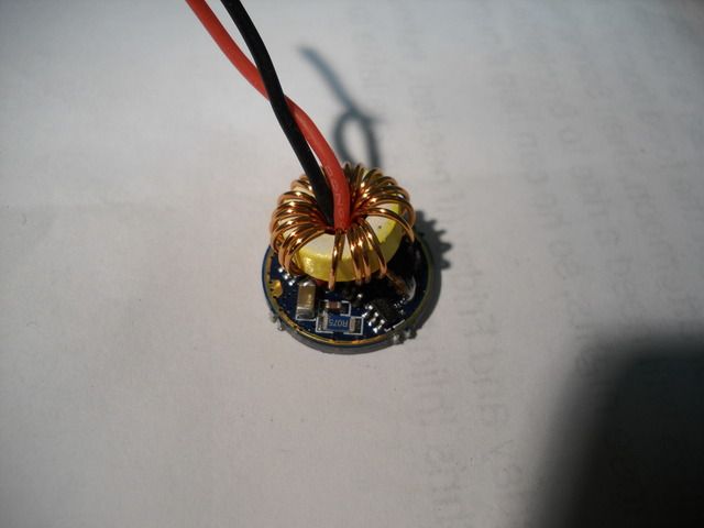
My camera doesn't do great macros, but heres my "best shot"
I'd say the inductor is about 20% smaller on this one. In the old version you could fit any size wire of your choice through the center hole, and in this one the factory leads barley squeak through.

Actually when this 2.4A 17mm driver came out it was probably the highest output 17mm available. The price is also incredible on this driver. It's really nice for the price.
Pretty much everything.
- Buck IC (if you're switching an FET gate with a lot of capacitance at high frequency, it requires a lot of power)
- FET
- Flyback diode
- Sense resistor
- Inductor
The problem is that we need everything to be small and compact. That means:
- Smaller inductor with higher DC resistance and lower inductance
- That lower inductance value means a faster switching speeds, which means more switching losses
No question about that. Your prices are unbeatable!
I know, right. A 17mm driver that is a true buck, multilevel brightness, and can be boosted to 3.7A with only the change of a resistor. All for >$5 bucks.. I really though my ship had come in with this board.
They are actually still not a bad driver. I'm just still a little twisted up over having to use extra cells now
I just used this driver in converting a MR16 canister diving light to LED with a custom pill. I have to report that the earlier recommendation of connecting pins 1 and 3 to lock the driver into high mode did not work on my current issue of the driver. Doing so, locked the driver on a lower light output mode (medium I believe). Since I only had the one driver on-hand to experiment with and the fact it was already soldered / potted into the pill, I removed the bridge and re-enabled the 3 modes to have high available.
My LD-4B, bought from MTN a while ago, has two stacked sense resistors. The top one is marked R620 (0.62 ohm). I haven’t desoldered the bottom one yet to look, but I think it could be a 1R00 (1 ohm) instead of R100 (0.1 ohm).
This follows from observing that high mode runs a Nichia 219C for 2 hours 40 minutes on a 1000mAh 18500 cell. That translates into an LED current of about 470mA, by my back of the envelope calculations.
If both stacked resistors were 0.62 ohms, that would be 0.31 ohms total, which would give a 3.1x lower current than a R100 resistor (2.4 A / 3.1 = 774mA). But the roughly 470mA actual current points to a total resistance of about 0.51 ohms instead.
The combined resistance of these two stacked resistors is given by
1 / (sqrt ( (1 / Rtop^2) + (1 / Rbottom^2) ) )
If the lower resistor is 1R00 (1.00 ohm), that’s 0.53 ohms total, for about 450mA current. (That’s the closest standard value 5% resistor to my estimate of 470mA. Close enough.)
From this I’ll make a wild guess that someone at the factory installed a 1R00 instead of a R100 resistor on one or more of these boards, producing an off-by-ten error (0.24A) in the output current. Whereupon some bright soul grabbed whatever fractional ohm resistor was handy and stacked it on top of the offending 1R00. Et voila!
I plan to replace the resistors on my next Digikey order.
Please desolder the bottom one to see what you really have. That buck IC has a 0.25V feedback voltage, so if you really have a 0.62 ohm and 1 ohm resistor the approximate maximum output current would be ~0.625A. I don't believe this is the case, however.
I would not recommend using these in a single cell setup. Use a 7135 driver and you'll be better off in most instances. The 7135 drivers are rock-solid-reliable, have better firmware options, and are smaller and less expensive. I have yet to see a buck driver that will outperform one of these efficiency wise at 2A+ with a white LED and a single lithium-ion cell. The buck drivers start out slightly more efficient depending on the vF of the LED and battery sag, but as the battery drains the 7135 driver comes out ahead.
The LD-4B driver generally will not give full output with a single cell because the buck driver needs some extra voltage overhead due to the extra resistive losses through the sense resistors, inductor, and FET. Because of this, and the fact that the battery will sag over time, the method of measuring current by runtime alone on a single battery is inherently flawed. The light will likely never output the full current, even with a full battery, and even if it does the current will drop significantly as the battery drains.

It turns out that my wild guess, while plausible, was wrong. The bottom resistor is in fact a R100.
When I reinstalled the R100 resistor, the driver at first worked at full output, but was stuck on high mode. After 4 or 5 minutes it got quite hot and stepped down to medium mode. And at that point, it started working in 3 modes again - High (now forced to medium), medium, and low. I turned it off and let it cool.
It then, surprisingly, started up at its former lower ~450mA set of three brightness levels. So now I have a nice 1+ watt light again. There’s something about how this driver switches between its nominal high setting and another lower set of modes that I can’t fathom. Maybe someday it will become clear what switches it from one personality to the other. I haven’t a clue.
To see how it would work at 2-cell voltages, since I don’t have a 2 cell light, I powered the driver directly from a 0-7.5v 0-5A power supply, at voltages from 3.2v to 7.5 v. At that time, it was in its ~450mA personality. It was noticeably a bit brighter at 7.5v than at 3.5 v, and cut off completely around 3.2v.
So, still scratching my head about this. It’s fine, though. I can use it to walk through the woods at night.
This morning the driver worked properly for once, after recharging the battery and putting it back in the light. No flaky problems. Great… but why?
Looking more closely at the driver and brass pill, the driver is a little too thick to completely fit in the recess in the pill, because of the thick inductor. So the ground ring around the edge of the driver contacts the brass pill on only one side. And the components on the driver board are of various heights, so that the inductor, which is off center, sits at an angle and this makes the entire board sit at a slight angle.
Because of that, compressing the spring and screwing the head firmly onto the body puts pressure on the driver to slip sideways so that it’s no longer centered relative to the brass pill.
The ground ring around the top edge of the driver board is about 0.4mm in width, and about 0.6mm away from it are some solder pads. It looks like, under the off-center pressure on the angled board, at least a couple of these exposed solder bits are candidates to contact the edge of the brass pill.
After I masked the exposed solder bits with electrical tape, I couldn’t get the flaky behaviors to re-occur even if I screwed the head on firmly. No more too-hot excessive current drain within a few minutes. No more lower than normal brightness modes.
So this is resolved, and I’m now happy with the driver. The only thing I don’t much like is the relatively poor regulation - it dims significantly as the battery voltage declines. But thanks to RMM for his explanation of why that can happen when this particular driver is used with with only one cell.