Thank you wight and Richard for the very detail explanations, and appreciate MRsDNF for the short summary too.
Ok, I learn something and I think I will risk another emitter later. I still have 3 more old XM-L with me and I can use them. Now when I come to think of it, it is also possible that when the driver was press fitted inside the pill somewhere has made bad contact with the pill (GND) and created short. I couldn’t see what happen inside the pill when everything was press fitted in it already, but what can I do is I will hook the driver + LED + battery outside the host and see if it is the driver or it is something else.
If I use just one 18650 to power the driver and all the three modes (L-M-H) work perfectly, does it mean my driver is fine or it doesn’t necessarily be?
You could use a ‘dummy load’ like a 1 Ohm 10 Watt power resistor in place of the LED. Then measure voltage across the resistor to see what current is delivered. ….saving another LED poof.
Why wouldn’t it work? Wouldn’t this be similar to a DD situation, e.g., awhile ago, I DD’ed an MT-G2 with a low ohm power resistor in series with the MT-G2 and using 2 x 16340s.
Correct me if I'm wrong but if you dont have an led hooked up to the outputs of a driver there is no load on the driver hence what are you measuring. I believe some drivers will be damaged without an led hooked up. I suppose it would be like measuring maximum horsepower of an engine on a dyno at idle.
Since the driver is current regulated, it is to check the driver current output. The 1 ohm load is approximately the Vf of an XM-L2 at 3 amps (3 volts) so should be in the ballpark anyway. (makes the math easy too)
(…I still suspect a ‘short’ (direct driving) somewhere in the current path to LED is frying them)
Four high power rectifier diodes(in TO220 package or similar) mounted on heatsink and connected in series would be a good simulation of LED,and very robust.
Because it would still pop LEDs. The resistor won’t drop enough volts to protect the LED from whatever the problem is. As I think I pointed out above, there’s really nothing to learn here [without an oscilloscope]: we know that the driver is bad!
Even though an LED does not behave Ohm’s law in current/voltage, you can still test a current regulated driver with a pure resistor load. The driver doesn’t know or care about the differences here.
Forget the 1 watt resistors(can’t handle the current) and just get 4-6 of the 10 Watt 1 ohm resistors for your test bench.
These you can configure in series or parallel as needed for various currents and voltages you are testing.
(2 in series gets you 2 Ohms, 2 in parallel gets you 0.5 Ohm)
Simply replace the LED in the circuit with the suitable resistor value and insure that it can handle the wattage/current. (as my example above to use 1 ohm to test for 3 amp at 3 volts to approximate an XM-L Vf)
Measuring the voltage across the resistor will tell you what current the driver is delivering to the load. (per Ohm’s law)
If you aren’t familiar with Ohm’s law, look it up, print out the table of formulas and stick it on the wall above your bench. You will eventually use it enough to memorize all the important relations.
I think that the purely resistive load sounds like a reasonable way to check drive current, but I’m not sure how accurately you can observe potential bad behavior like spikes when you just have a resistor on the output. Maybe led4power’s suggestion is a decent option? I don’t know. Observing bad behavior is really what I’d be interested in.
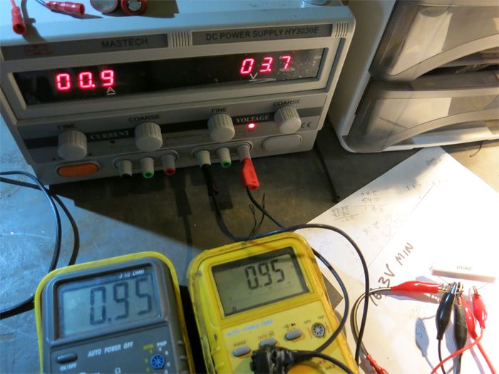
Again if this is not the right thread I apologise but I thank you all for trying to teach an old dog. I've printed out Ohms law and have it on the work bench. I have set up a 3 amp 7135 driver to my 10 watt 1 Ohm resistor and had a play. Everything is working and touch wood I have not had smoke yet. Its magic and I'm excited. All I need now is some more resistors to have a play with more current.
Those are schottky diodes,they have 0.3-0.5 Vf,so you need more than 4 of them to get 3.5-4Volts Vf.It's simpler and cheaper to buy normal 0.7V diodes.
Guys I tested my LD-40 outside the flashlight host, hooked it up with an used XM-L with two 18650 in series, turns out no LED was blown and all the modes (H-M-L) are working well.
So no more complicated technical discussion about the driver… all the mess were simply caused by my own stupidity. Something was shorted when I assembled the driver into the pill and killed so many of my emitters. Have to be extra careful with batteries in series next time.


 Sounds harsh aye.