Damn it, it does work! :D I had a bad connection somewhere in my set up, but I got it working and it is regulating it perfectly! I'll get a picture up in a few minutes. After that I will leave it on til it burns. :evil:


I think it might be working because the current from Vdd to ground is very small so the power loss is in that part of the chip is low. I am surprised that the IC didn’t blow and when you try it on low it may still poof. The way that mod was done in the poor man’s multilux , one of the LEDs was placed between the batteries and the driver to drop the input voltage to the IC. The version I did last summer replaced the 7135 closest to the led+ with a 7805 (2981 for 2cells) voltage regulator and rewired the the traces to give 5V to the IC. 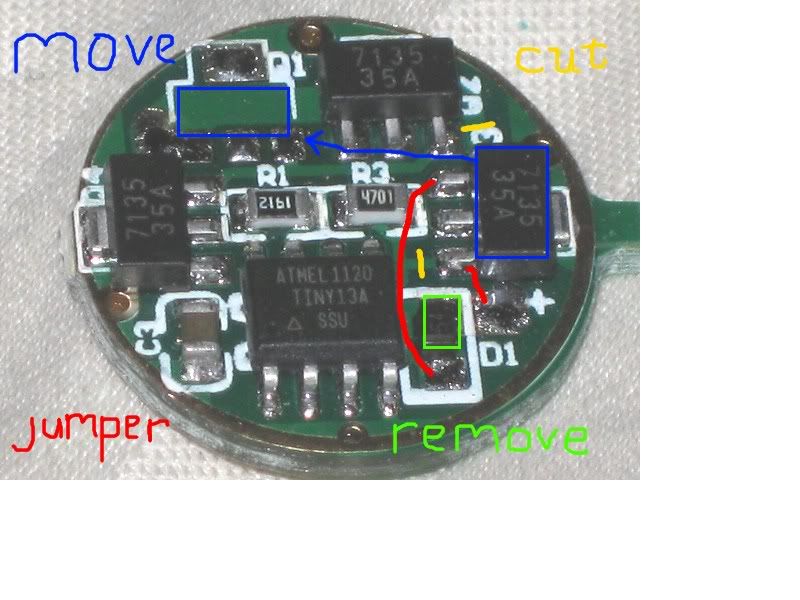
The 7135 in the blue box is moved or removed and the VR chip goes in that location.
Instead of removing the diode it can be used as the jumper from input + to the VR chip. This provides the whole unit with reverse polarity protection.
All modes worked and I also tried it on 6 AA (Energizer lithium) but I only left it on for a minute or so.
Any update on how it went?
There were some who you said “you can’t do that” to me so I won’t say that to you but just suggest you carry a spare which you probably do anyway. I did a fair amount of testing with that mod and all I can say is that whenever I exceeded 6V to the driver or chips something would fail, usually with a puff of smoke and a fzzzt. Just skimmed that thread and the highest I went with complete success was 3 LEDs and 9 nimhs. Like you I was looking to eliminate the power loss from the high currents required by parallel mods and use the stock switches on my lights.
No, I had to recharge some batteries first. But it is currently running and has been running for the past 2 minutes.
12 minutes in and still alive. 
The duck is on to something with the regulator. Also, as long as the Vf of the LED string is ony about 2V or so less than the battery voltage, heat should be manageable. I may try this with an MT-G2 for a poor man’s 6V driver. Efficiency will suck, but it gets the job done.
The MCU is likely the first to ‘sign off’ if you run without voltage regulation.
So far it has been running for 30 minutes, and no problem.
I wonder how robust it is during on/off cycling. Just looking for a way to make it fail. If it doesn’t, great.
@Rufusbuck, my plan is to let it run for an hour like this (currently been running for ~45 min) and then do some on-off cycles, probably 100 or so. If it survives that then I would be confident to say it is relatively functional. Of course I may want to try it with more than one 7135 at some point, but that means I have to find a heatsink.
From what I can see of Scaru’s wiring, all of the battery voltage after sag is dropped across Vdd-Gnd. The current splits with the vast majority going to led+back to led- on the chip and through the chip to Gnd and only 200 microA goes through the Vdd pin to Gnd. So the voltage drop across led- to Gnd is whatever is left after the drop across the two LEDs.
While its running can you measure the voltage at a few points to demonstrate this Scaru? Thanks.
So where should I measure voltage?
More chips should drive the LEDs harder but be easier on the chips due to lower sagged voltage so you should only need to sink the LEDs. Maybe just clamp them to some stock with a clothes pin.
Just for completeness, measure across each led, then both, then across the chip both from led- to gnd and Vdd to gnd. And one more from 1st led + to gnd. That should be all of them. Later, if you desolder the Vdd pin you could measure the current there and see just how small it is. I’m betting this is the only reason this works.
Ok, so it ran for slightly over an hour and no problem. Here the measurements are.
Voltage across first LED=3.252
Voltage across 2nd LED=3.217
Voltage across both LEDs=6.43
Voltage from LED- (the 2nd LED near battery -) to battery - =1.617
Voltage from vdd (batt +) to gnd (batt -)=7.97
first led (far away from batt -) to gnd (batt -)=7.92
I'm going to hold off on desoldering the vdd pin until you confirm I didn't screw up these measurements.
Since when is everything perfect but those look close enough. So all the voltage does indeed drop across Vdd. But only 1.6V across the other part of the chip.
It’s impressive that the 7135 is OK with Vcc at almost 8V. I’d guess it is low current, and may be protected internally.
What is even more impressive is how the MCU is handling it. Most of these do not have over-voltage protection on the Vdd pin.
The drop across the L- and Gnd is not too bad. With a 1.6V drop at 0.35A, each chip is dissipating 0.56W, which isn’t too bad on its own. With eight chips, that’s about 4.5W of heat for the driver to dissipate. This is quite a bit of heat on a 17mm board, but seems manageable.
Based on this, I’d say a longer term solution would be to has some kind of regulation for the MCU. Using a 7805 is good, or use a simple zener regulator.
Ok, I have done 100 on-off cycles and so far everything is still alive. So should I desolder the vdd pin to measure current?