I wish there was a place locally to buy those resistors. What am I going to do with 200 of them?
Funny thing, my wife saw me looking at the band of resistors on the Fasttech site from a distance and thought it was a diamond necklace. When she got closer, she laughed and said, “Oh… should’ve known.” Haha.
If you have some drivers that you’ve removed/replaced (or any other electronics that you’re throwing away) that have surface mount (like maybe laptop packs), you might be able to scavenge and find some resistors that you can use off of those?
Or…. you can buy only 1 of those big emitters, remove all resistors, replace with solder bridge/blob… this host and reflector (and even the driver) are good match for it. Just giving another option for upgrading…
Also, the emitter doesn’t sit close enough in the reflector. The reflector is aluminum and there’s no silicone centering ring. I also have no Kapton tape.
How would I get the emitter closer into the reflector without leaving the pill only partially threaded in the tube and is there an alternative to using Kapton tape to keep it from shorting?
You still may need some kapton tape, the centering ring won’t necessarily keep the reflector from shorting onto your MCPCB solder points. Kapton is a brand name though, the Chinese unbranded stuff will also work: http://www.fasttech.com/search?kapton%20tape
But even with those things, it wouldn’t bring the emitter deeper into the reflector. Protection aside, how would I physically move the reflector and emitter closer together? The top, outside edge of the reflector sits on the lip of the head so it can’t go down any farther.
I think the typical solution is to purchase copper disks and solder a Noctigon or SinkPAD onto them in order to gain a little height.
I believe that the typical source is this person on Etsy: SupplyDiva - Etsy
You can certainly purchase sheets of copper locally (craft store maybe?) and cut them yourself, it just won’t be as pretty and will require more of your time.
Was the emitter already not far enough into the reflector when the light was stock?
Since it looks like the pill is designed to thread into the head, and since the reflector apparently is designed to be in a fixed position, it seems like the light is designed such that you have to adjust the pill position by screwing it up until it’s snug with the end of the reflector? Or is that not the case?
If that is the case, then it seems like the mfr should’ve provided some means to prevent the metal reflector from shorting to the solder points on the star already/stock?
For this particular light, the pill screws in the direction of bezel to body so I could theoretically just loosen the pill, thus raising the height of the emitter, but then the pill would not be securely tightened all way. I think what I’m going to try to do first is try to find some thermal tape at a local hardware store (which has proven to be a little difficult where I am in Taiwan) and then tape up the bottom of the reflector and just do trial and error with loosening the pill to the desired position. From there, I’ll see how bad it is to leave it untightened and make adjustments accordingly. I just don’t want to desolder the emitter and put copper in between because it’s also pasted down with thermal paste.
I’m not sure precisely what your goal is for the thermal tape, but please know that it is not an effective way to help cool a power LED.
Also know that whatever stock thermal adhesive is in use is no good. I would consider replacing it with something better.
And finally, also know that an aluminum MCPCB isn’t the greatest thing after 3A or 4A. djozz has posted some helpful data here - 6x 20mm XML-ledboard comparison
As you can see, at 3A you’re already benefiting something like 14% in light output by switching to a DTP MCPCB. What djozz’s output graphs do not show is that at higher drive currents the LED temp is going up and the LED does not like it.
- The thermal tape was just so the aluminum reflector doesn’t contact the solder points on the star. I was told that kind of tape could hold up to the heat fairly well.
- I have no thermal adhesive but I guess I can try to find some.
I wasn’t planning on driving it too far past 3A. I was just going to add that extra R300, which (by those calculation links you gave me) would bring it to 2.8 or 2.9 if i remember correctly.
My goal for this light is just to get the most out of what is already there. I don’t really have the expertise to do any extensive modding. I just want to drive the current up a little more and get better placement of the emitter in the reflector. I really do appreciate all of your advice and comments though. I love this place.
Is the “thermal tape” non-conductive? Is it difficult to get kapton tape (which I know is a non-conductive insulator, and which I just used)?
You didn’t really answer my question, but it sounds like with the stock light, the manufacturer didn’t bother to get the pill to push up against the reflector tightly, but I think that, depending on how much you have to unscrew/loosen the pill in the head to get it to butt up against the reflector, it should be ok, because, from your pics, the driver has a spring, so once the batteries are in, they should snug up the whole thing.
There are pics in my other post that I linked earlier:
This is for the Roche LS-01. In those pictures you can see the small gap. There’s no centering ring or anything that would keep the emitter from contacting the reflector, which is why wight recommended the insulation gaskets from FT. I did mess around with the reflector a bit and tested it in different positions of depth after I temporarily taped the reflector to prevent shorting. If the emitter sits flush inside the reflector, it improves the beam by increasing the brightness of the hot spot and reduces the beam rings by quite a bit.
Ahh! Ok. I had the same experience recently with a light, and used kapton tape on the reflector and removed a plastic centering/insulation disk. Mentioned here: Resistor mod for Meritline X8 Clone? (AKA Small Sun ZY-T614). I just added some pics in post #65.
Doing this made a huge difference in my case, eliminating a dark spot in the hotspot.
In my case, it’s also a pill that screws into the head and since I am no longer using the vinyl insulator disc, I had to unscrew the the pill quite a bit (forward, towards the reflector, but not completely unscrewed from the head), but it’s fine. I think that there is a little rattling, maybe because the pill is unscrewed, but I’m not 100% sure if it’s the pill or the reflector that’s rattling (haven’t bothered much since the light is working well now).
I should be getting my resistors in soon… but one question before I start soldering. I’ll be getting R330 resistors and the current stock resistors are R200 and R300. When I add the R330s, should I put one 330 on the 200 and another on the 300? Or stack two 330s on either of the 200 or 300? According to the Ohm calculator, a combination of .25V and resistance of R200, R300, R330, and another R330 would give me 3.59A. But does it matter how I stack the resistors??
Sorry, I’ve been busy and did not have time to respond.
Electrically they are in parallel (on each end the terminals are all connected together).
I’d stack them side by side rather than in one big stack. In this case your total heat dissipation on the resistors isn’t super-high, but it will be about 0.9W. The R200 will be dissipating over 1/4 of that (feel free to do the math yourself, I’m not…). In order to prevent burning/cracking/whatever of the resistors we want to spread the heat out as much as possible.
Well, I got my parts in today and did my first mod by soldering on two stacked R330s on the Roche LS01. According to those number calculators, it should be pulling 3.59A. It was a long and difficult soldering job since the resistors are soooooooooooo incredibly tiny, but I got it done eventually. Here are some side by side comparisons of the old high, mid, and low pre and post mod.
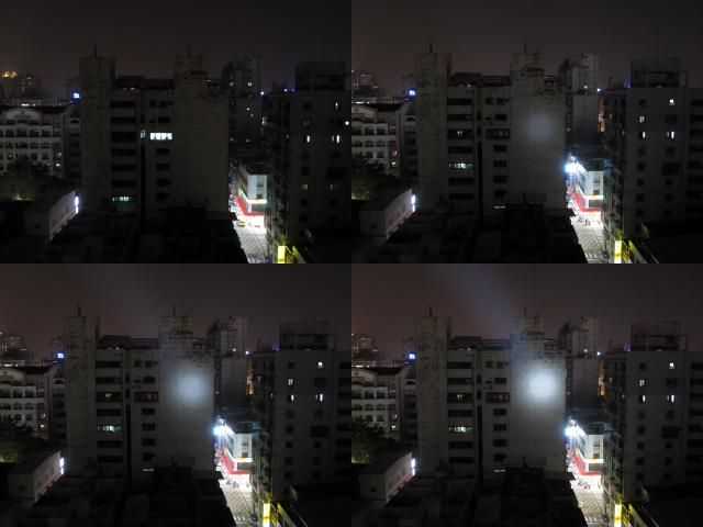
This is Pre-Mod: Control, low, mid, and high
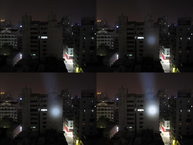
This is Post-Mod: Control, low, mid, high - not as easy to tell the difference.
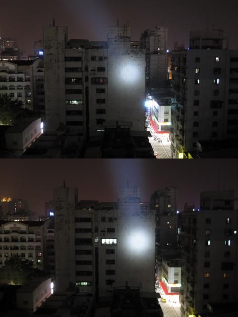
But in the side by side pre and post on highest mode, you can see the difference better.
After all of this, sometimes, the light doesn’t turn on if I turned it off on high mode until I give it a light shake. I made sure I didn’t flow the solder on the adjacent resistor, but who knows how close it really was. I even used my jeweler’s loupe to double check.
Looks like a worthwhile improvement. I wouldn’t normally refer to 3.59A as the current “pulled” but the current “provided” to the LED. I’m not necessarily following a rulebook, but I think that’s convention and helps avoid confusion. (current “pulled” by the buck driver [tailcap current] should be lower, some people will guestimate output current based on that number if you provide it)
The Roche LS01 is a tail-clicky light, right? So when you operate the clicky it cuts the circuit…
I misread your post. Now I understand. Hmmm.
Let’s try operating it with a DMM set to amps instead of the tailcap. Just tap the probes in order to step through the modes. See if you have the same problem with “no turn on” after turning off in “high” mode. If your DMM hasn’t been modded with thick leads don’t worry about it: continue and do the test anyway.