I will say the double click after step down is probably a bug I mentioned to TK and in thread. Probably could be fixed in firmware if someone is so inclined
Oops!
Just fried my Lume1. Accidentally put the battery in backwards. DARN! ![]()
Guess I really am going back to the original driver.
User name checks out. ![]()
I wonder the board could be easily modified to have pads for a polarity protection fet that could be easily solder bridged for people that don’t want it.
I just completed my FW3C and Lume1 driver successfully. And it performs flawlessly! I’m actually going to use one of my FW3 lights again! The soldering of the aux board wasn’t that difficult…. a needle like soldering tip and a steady hand did the job. Thank you for making this possible… Edit: Preforming almost flawlessly. Visible flicker on moon and the few steps above that. And moon is not as now as the AMC based driver. Both a pity, but not deal breakers though.
Another thing… can someone please redirect me to a page where it explains how to do the thermal calibration of the driver? I think I remember something about leaving the light to settle at a known room temperature, programming that value, and then setting the temperature threshold.
Brought to you by our own M4D M4X
")
Thanks
One thing to note: almost all other drivers uses the on-board the MCU temperature sensor, which has a +-10C accuracy, hence the necessity for the calibration procedure. One of the features of the Lume driver is that it uses a dedicated high accuracy and low drift temperature sensor IC which is nominally accurate to +- 1C across the range from -40 to +125C (with slightly more drift below 0C and above 70C). I would recommend not changing the calibration of the temperature sensor and leaving it as is.
In addition, Anduril has a voltage correction factor calibration mode - this is only applicable for other drivers which may use some sort of Schottky diode to Vcc where the voltage measurement depends on the V_fwd_drop of the diode. The Lume driver's MCU has a regulated Vcc and is typically very accurate, so there is no need to do any voltage config as well.
This might be a dumb question, but would this driver work with other lights that have an e-switch? For instance, a C8F? I’m building a red triple, and the super low Vf of red leds is perfect for buck/boost and using a a low output cell for direct drive to avoid blowing up the leds. I don’t own any FW3 lights so I’m not sure if this exclusively works in that light even though I know it was designed for that light. Has anyone used this in something other than a FW3 series host? What about in a e-switch light with a single low vf led like the sbt-90.2 or 3v xhp50.2? Thanks!
Edit: I’m a dummy, Loneoceans and the freeman already answered this on page 6 of this thread.
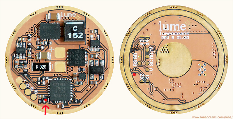
when you say “connect the e-switch where the red arrow is in the diagram” do you mean this diagram?
How does one connect the 4 wires from the e-switch on a c8f to this one spot? Appreciate the help
I agree, it’s not huge but not small either. I would definitely call it significant.
And 5A ain’t much. At higher currents it’s going to be worse than that.
But then…I’m probably on the more extreme side of low-resistance crowd and I didn’t buy the lume1 because its resistance is already too high for me.
There is no boost when you have voltage input higher than output voltage, that is exactly the opposite of boost and there cannot be boosting in such conditions.
To boost when the voltage of the cell is low requires current for that matter, and why would one expect lots of current output when the battery voltage is low already, by that point the cell can’t deliver but little current anyway, you also have to add all the resistance (like the voltage drop) on top of that low voltage already.
This was referring to a picture I posted but the link is dead.
You just need 2 wires from the e-switch, one to be connected to the ground/negative and other wire to the place on the driver as posted above.
Oh wow a pad that is 0.5mm round.
It has the biggest eswitch pad of any driver it’s just on the wrong side cause it wasn’t made for other lights. ![]()
![]() Reckon is it just as big as the driver it wishes to replace.
Reckon is it just as big as the driver it wishes to replace.
This is buck-boost driver, no matter how it works at the moment.
I said that I see no improvement of stabilization compered to stock driver.
3A substabilized until 3.1В , it is the same result I can get with linear driver.
Please tell me what is the current in the first mode of lume1 with stock settings? Also 350mA?
Where should my last lume1 driver go?

One of these 3? Or someone else’s light? lol
I have installed my last Lume1 in first release FW3A, lighter anno, black clip and more tactile button. 219C 5700K elas main emitters.
Really like it compared to all other mushy switch versions
The bottom left one is my 1st gen with best switch. Shaved LH351D 5K 18500 tube. I dont like the anno color but the switch is too good to get rid of by comparison.