As said, host 2 did around 6 amps with the qlite. It has 8 additional 7135s.
Hi. Thanks for the recommendation. All springs are already braided.
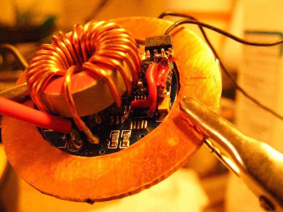
By the way, the Zener modded Qlite was sourced by Richard at RMM.
Hi Old-Lumens. Thanks for your feedback. I appreciate. Can you maybe direct me to a thread where heatsinking has been applied to the driver?
Ok, so I’ve found this post from Richard, which answers 1 of my questions…
“I don’t think you’re missing too much! This is not the optimum solution, it is one that was designed to work with existing drivers and still be able to fit into lights with small 17mm driver compartments. With IMR 18350 cells I haven’t seen much any thermal throttling when driving an MT-G2 at around 4.5A when actually installed in a host. With two 20Rs sitting in the open air you see the 7135s begin to thermally regulate (cut current) at less than 30 seconds. The closer the input voltage is to output voltage (look to emitter vF curve) the less heat the 7135s will have to shed, this means that batteries with a little more voltage sag may actually be better for this setup.”
Old-Lumens, regarding my heat sinking question, I’ve found this post from you which answers that question…
“After doing many of these, I feel that the 7135 chips need heat sinking to keep them from getting too hot and dropping out. As to the best way to heat sink them? I do not know. Fujik isn’t enough. It needs to be something like direct to metal, so I use copper and it seems to help, as the light does not dim near as quickly. When I say quickly, I mean that with no heat sinking, pushing the MT-G2 to 9 amps, causes dimming in seconds, where with copper soldered to the outside tabs of the 7135 chips, it lasts for a couple minutes before dimming.”
So, which regulated driver will do well in driving a MT-G2 around 6 amps? On the other hand, its probably just better sticking with the DD driver when pushing high amps. The voltage sag on the batteries will be high and regulation will probably not be sustained for very long. Whats the opinion here?
Disclaimer: I haven't read anything in this thread except for the OP. I can tell you that your 7135s are overheating and derating the power. The adapter and high drain cells are the problem here. With that adapter you aren't getting hardly any thermal interface with the host. Get that driver in contact with your host and switch to some weaker cells and you'll be in good shape.
I have host 2 and 3… I put 22mm BLF driver from RMM in host 2 but never get it to work right.
also having problem with host 3 too, it was fine for awhile then work on and off… :~
Shrick wrote:
. . . Regarding the Qlite driver thats performs so bad… I have a C8 running an MT-G2 with 18350s doing close to 6 amps. The C8 does not show the extreme drop in output? Why was the effect so extreme in this host?
You never responded to Post 3, but my guess it you have the driver in the C8 mounted directly to the pill. For your Host 2 you could do something like this so that the ground ring of the driver has a good thermal bond to the pill.

18350s sag a lot more under load than those hot 18650s do.
Can you maybe direct me to a thread where heatsinking has been applied to the driver?
This is called potting when components are embedded in a solid to aid in thermal transfer of heat. Check this thread
ImA4Wheelr, my humble appologies that I’ve missed your post.
You were actually the first to spot the problem! Much appreciate your feedback, and yes, you’re right, the driver in the C8 is directly mounted to the pill. The build above was my first build with an adapter board. I was not aware that such ‘little’ contact the driver has with the pill makes such a huge difference in keeping the driver cool?! Thanks for your recommendation on the heat sinking - appreciated.
Thanks Rufusbduck, appreciate the link. I must also say, I’ve made use of these silicone thermal pads. It did not work well. But, I’m thinking now… I’ve placed the pads at the front of the pill, then the driver, then the adapter board. Because of the extreme heat coming from the MCPCB, this might have had a degrading effect on the driver? I have not really tested how fast heat is absorbed by these pads though. Maybe they’re a gimmick. I should do some tests on them.
Thanks Richard. It also seems the direct contact of the driver with the host in the C8 makes a big difference in conducting heat away from the driver. I was not aware that the effect will be so big? The driver is connected to the host with such a small area? Its probably a combination of the “not so hot 18350’s” & the driver not having contact with the pill?
On the 9 amp 7135 drivers I do, I use a thick copper disc and glue it flat down onto the 7135 chips. That driver is easy, because all the chips are on one side, but on other drivers, you can use copper around the outside, soldering to the back tabs, as you stated. Use as thick of a piece as you can bend and you can soften copper too, with a torch, so it bends easy. If you want thick copper, you can always get hold of a 1" copper plumbing coupling and split it, then heat it till it turns black and then it will be super soft, so you can cut, bend and shape it.
For heatsinking of a nanjg105c driver I did that once using copper tubing. Not sure if it is applicable in your flashlight but it is described in post #35 of this thread: https://budgetlightforum.com/t/-/22447
Djozz, thanks for the link. I like what you did there, its a good example.
Old-Lumens, the 2nd part of your recommendation, for the drivers having 7135 chips on both sides, its difficult for me to picture exactly what you’re recommending. Do you maybe have a link to a thread that illustrates “…use copper around the outside, soldering to the back tabs…” Thanks for your feedback, again.
Well, I know somewhere there are photos, but it's been so long, I don't know where to look. You take a piece of copper sheet and cut a strip about 3-4mm wide and long enough to circle around the outside of the 7135 chips on one of the Qlite or NANJG drivers. Then wrap it around the driver, like you are adding a wall around the chips and the copper touches the outside of the chips where the back ground tabs are and solder the copper to the tabs. Do that on both sides of the driver and then you always can add more copper with another wrap around the whole thing. I will try to hunt for pics.
Old-Lumens… No worries to hunt, its clear now. Thanks a lot.