Why does Simon rate his L6 so high at 3800 lumens? Is he just basing that on what the emitter can achieve?
My stock neutral white L6 is only pushing 2800 lumens with Keeppower’s.
Advanced Knife Guy on youtube rated his at 3278. Didn’t think my calibrated TA lumen tube would result in so much difference. Glad I’ve got something near accurate though
Maybe Simon paid someone to measure it and that’s what he was told. Or maybe he measured it on a device that read a bit high. It’s hard to say.
I think the stock CW version is around 3100 to 3200 lumen. NW versions might measure a bit less. They may not actually be less, but they will probably measure less.
I’m surprised AKG, mhanlen on this forum, got close to accurate numbers. The last I checked he was using a home built lumen tube type device without a calibrated light source.
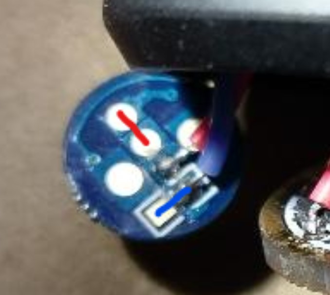
Thanks to this post as well as Matt Smith’s I was able to boost my Convoy L6 and add LED’s to the side button. My Convoy side button has a slightly modified PCB, so not only did I need to jump the positive connection for the LED’s, I also needed to jump the negative circuit as well. I took a quick look at the traces and by default the negative blue cable no longer connects to the LED’s “-” circuit. Creating a jump from the blue cable to another spot on the board right next to it creates the common ground needed. Just FYI if anyone else is looking at the photos and wondering why it doesn’t work. It took a little testing to make sure I was indeed getting the positive signal to the LED circuit. I’ll post a photo later.
As promised here is an image of my latest Convoy L6 switch PCB. Apologies for the poor image. But basically the red line still follows the original post, the second blue line is the one needed to jump the ground to the negative poles of the LED location. If you have the new PCB, it won’t work without jumping this. The 2 larger contact points are also negative terminals, so you must be careful the red wire doesn’t touch it and short out the LED.
I have the same TA driver in three flashlights. I would like to have a lighted switch or maybe also aux leds on them. Thanks for the nice picture with comments.
Does indicator led mean that the switch leds connected with a 4.7K resistor to R2 will be MCU controlled, with low, high and off settings in Anduril?
On a flashlight with lighted switch I had a problem with the led still glowing when off. So if I connect a lighted switch to the positive wire of the driver I always need an additional resistor, right? That might explain the glowing led I had because I connected a lighted switch to positive directly.
On my particular driver, which was built in 2017, all the outputs on the MCU were being used due to it being a 2S (6v) driver build. There weren’t any extra outputs to control a switch LED.
On a 1S build (3v) you can use the “indicator” function because it is connected to the MCU. You would need to ask Lexel for more details on that. He may even be able to use it on a 6v build now.
To power a generic switch light whenever power is connected, you just need to source the power between the battery and the main led. Not after the main led. You probably tapped into the power after the main led which will bypass the FET and make it glow.
If you have a driver where there is no source of power, you have to tap into the main led on the battery side of the mcpcb and run that wire back down inside the flashlight. I did that on this S70 build.