Thanks, Helios. A decent driver would be nice. I am sure with PWM the runtime would be much better too.
Update: I used a spare 1A Nanjg AK-47A and it seemed to do the trick. Now to remove those redundant 7135s…
Thanks, Helios. A decent driver would be nice. I am sure with PWM the runtime would be much better too.
Update: I used a spare 1A Nanjg AK-47A and it seemed to do the trick. Now to remove those redundant 7135s…
Around 2.54V is needed for 5mA, 2.48V for 1mA depends on the LED of course, this is based of a first generation XM-L.
I just discharged a purple xtar 2600 and it stopped at around 2.3-2.4V.
I tried it several times, so 100mA trips the protection
From what I’ve read 2.5 volts is minimum so is this to low?
This is okay, it might harm the cell a bit but hey if the protection would kick in earlier we couldn’t use the batts. You have to think of the voltage sag under load.
I first discharged the batt with 1A and after the protection had kicked in, I put it on charge for a second and measured voltage it showed 3.2V…
On 0.1A it showed after reresetting the protection 2.8V.
So I am okay with this.
The thing with the low current should still be investigated a bit…
So do you think my theory might be correct that the PCB is not truly breaking the circuit but rather stepping down the voltage to near 0?
sb, may I know the source of your XTAR batteries?
I remember there was news about a lot of XTAR fakes even their chargers.
Sure hope they’re not fakes. Because they were samples for review that XTAR sent me directly. ![]()
If had not already charged the battery I would just connect it to a nanjg after discharging it with 0.1A. The few mA standby curent should show if the theory is right.
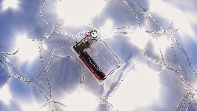
Urgh, my Trustfire are horrible for this sag. I can’t even discharge at 200mA without the protection kicking in at 3.2V.
sb, maybe you need to disassemble one of them to take picture of the circuit and IC used.
Hopefully someone expert in circuit can explain it.