Duh, read the title dufus! Sorry, a 105C has eight chips and can have eight separate outputs if the output trace is cut between each of them. Don’t forget about the vias connecting the two sides.
Yes there are vias to drive the other side of the board.
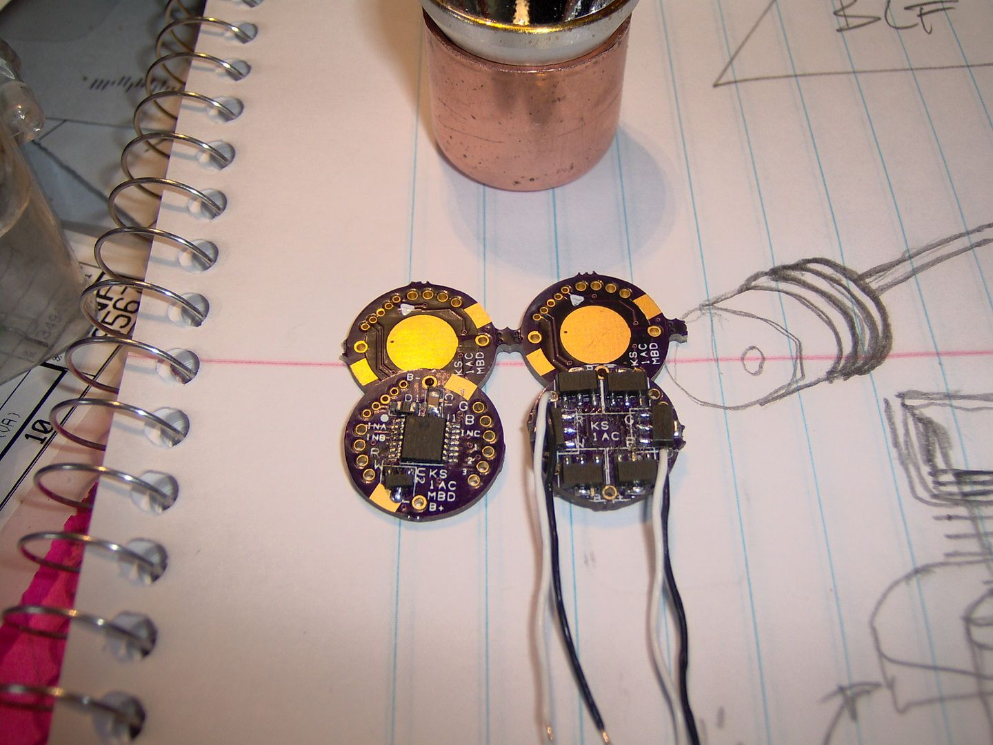
It’s a 8*7135 Nanjg 105c.
I need to separate both output and input of the 7135 since I want to control each output separately.
I will have to check the ATTiny13A pins and see how many I/Os it has, then cut the correct traces and make new ones to the MCU.

Cutting output leads (separating AMC’s into pairs) will allow you to drive about 4 red leds @ ~700mA, all in the same mode but if you cut input leads, even if MCU has spare output pins that you could use it would be very difficult to control leds individually, behaviour of all leds would have to be defined in one mode and if you want to change something that would have to be done in other mode for all led’s again and you would have to write your own code to redefine output pins of MCU and driver behaviour.
But I like the idea of driving 4 red led’s, same behaviour for all of them in particular mode, and it’s easy to do. Up to 8 led’s with 8 additional 7135 chips ![]() hell of a tail light
hell of a tail light ![]() hardest thing would be writing code for different “blinki” modes…
hardest thing would be writing code for different “blinki” modes…
Well so far I see the code part as easy, did not try it yet though :bigsmile:
But it should not be harder than writing computer software.
So yes I will have to and plan to write my own code to make the blinkies and UI I want.
The body is ready, just have to glue the heatsink plates, MCPCBs, lenses so it holds together.
Not sure yet if I will put the driver inside or get 3 wires to it and have the driver outside with the battery pack.

Could theoretically put out 360lumen at 2A total. But looking from a distance at the 10° or even 30° lens at it’s full rated power 1A is not something desirable. So the heat sinking is a little bigger than what I used for continuous 1A testing but nothing that would probably handle high currents. The middle fake lens is the original one the light had.
40g right now.
Nice build :)
I suggest using pin5/PB0/OC0A for the second light, so you can use hardware-PWM, shouldn't be difficult. Having 3 or more individually controlled LEDs requires software-PWM and that is not really desirable... I did that for my RGBW light and am not too happy with it.
Any chance of piggybacking a second mcu after programming them so that each drives a pair? Could it use the same resistors and capacitor + and gnd while floating an I/O wire to the chip?
Yeah I will check the I/Os it can for sure do 2, but as Jones said it might not have 3x PWM. And I do need PWM to bring the power down.
Rufus: yes you could probably piggyback them as long as they don’t somehow interfere with each other, but you will have a problem to solder the I/Os in a way that they are not connected but separate.
I was a bit afraid the light will look like a hybrid but so far it looks like an E.T. which is fine ![]()
Hopefully it will have enough flood as well, the original crappy lens did make it very floody with a lot of losses.
How much does the Nanjg105c eats when it’s in a offstate/sleepstate? Power on but output set to OFF.
Few uA?
Yes ATTiny13A has only 2 PWM outputs, PB0 and PB1.
25/45/85 has PB0, PB1, PB4, should be 3. But it says 2 PWMs, so it’s a little tricky but possible.
There is always software PWM right, DrJones, what’s not so good about the software PWM?
Nanjg quiescent current is about 170µA, mainly due to the voltage divider. Eats an 18650 in 1.5 years :)
Disadvantage of software-PWM: much lower PWM rate and maybe some slight flickering on very low levels (depends on how exactly you do it).
Yes, ATtiny25/45/85 provides 3 hardware-PWM pins.
Edit: Just got rid of that slight flickering in my approach.
Getting a couple of kilohertz out of ‘software’ pwm on several channels by using a timer interrupt isn’t impossible at all… Especially since there is so little ‘other’ processing that has to go on and none of it is super time sensitive… Have you tried it using that method?
Thanks for showing this. I myself get confused on the boards I’ve seen and used. Now I know some of it.
PilotPTK: Getting, say, 2kHz PWM with a resolution of 256 levels requires a timer frequency of 512kHz, at 9.6MHz that means at most 18 instructions per interrupt call... With ASM that may work, but in C... The ISR's pushs and pops alone take more.
Yeah, I suppose you’re right… I’ve been spoiled using DSPics, PIC24s and STM32s - I often forget how low the clock rates are on regular PICs and TINYs…
That’s the rude and crude way of doing it. You can do it with only four interrupts (max) per 2kHz cycle. You pre-compute the required timer intervals and LED pin masks. The first interrupt is the start of the cycle. You turn on all the relevant LEDs, program the timer for the interval required to turn off the shortest on-time LED (s). When that interrupt happens, you do it for the next LED to go off, etc. The difficulty is very short intervals between required OFF ticks might be shorter than the setup time between states. If you limit the intervals to a fixed set (say powers of two) it can be quite efficient.
Yes, I know that method. But I wanted some fine ramping which implies PWM values near 0 and near each other, so I'd run run right into those problems. Also any change in the PWM values (which ramping does a lot) requires sorting them, and that also takes quite some of the precious program space I wanted to invest in fun modes... (here)
I changed that firmware's modes to something more suitable for my RGBW-MCE, but I need to invest more time to get the color cycling to work (so that I can tap the button to select a color).
Ah, that’s the project I meant in the first place 0:)
DrJones was my second guess :bigsmile:
I’ve checked the mutiple outputs online before many times and they always use ATTiny 45 or 85 for RGB LEDs. You have RGBW you use 4 channels of the 45/85? I think it has 4 but only 3 pins for them? It’s really confusing from the datasheets.
Why not pair two drivers together or use a bigger chip with more PWMs?
So the linked project light of NightCrawl has 4x software PWM on ATTiny13A?
What was the pain with it, the problems to control 4 LEDs at once from ATTiny13A?
Memory, code space? Some limits of Atmel and their chips?
Yes, the ATtiny25/45/85 has 4 PWM channels, but two of them join the same pin, so you can only use 3.
Pairing drivers can be done, but that requires some sort of communication between them.
Yes, the driver for NightCrawls quad (and my RGBW) uses 4* software-PWM. My approach is sort of ugly and dirty but quite fast. It required a quite different program structure (compared to my other firmwares), sort of around the soft-PWM.
Time to try out the PIC12F1501 …
Errrr…. the 16f1503 works. 4x hardware PWM for those not familiar with PIC’s. The ATtiny 24 would work for that as previously mentioned. I like the PIC16f1503 because it comes in the 14 pin TSSOP pkg. for almost the same size as the ATtiny25 skinny SOIC8. Not a big fan of the DFN or leadless style packages.
EDIT: Oops, thought 12f1501 was a typo, apparently not, can’t keep up with the times!
![]()
Yeah but where do you get the IC, PCBs, programmer, software? ![]()
2x PWM is enough for me right now and the ease of using Nanjg105c.
Hard to beat the price with anything else I think.
It really only makes sense to do the pcb thing if you are doing multiple projects, or need to hit a really small form factor. OSH Park does small pcb boards for cheap, and they ship internationally. It’s definitely a process to do all development stuff ![]()
If you can cut traces and jumper your way on the 105C, then there is no way to beat that on time or cost.