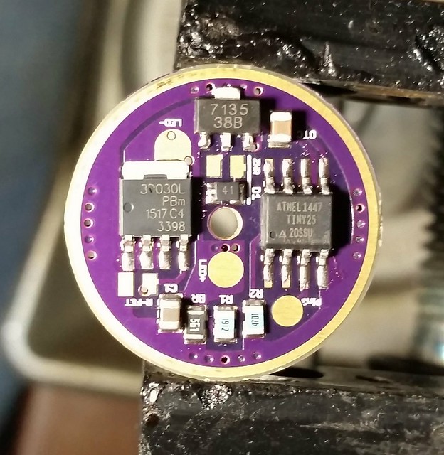
Just finished the basic build on the 22mm version of this board, it caught me by surprise with a new set of pads called Rfet. I did not populate it because I am not using the Vishay FET, I am using the standard LFPAK56 FET on this build. From reading many threads, it appears that the Vishay FET has a better state of high conductivity/lower resistance during a nearly fully driven state and it was causing the issue with the full to moon flicker. I also did not include it because I could not find a reasonably solid value for that resistor, it looks to me like 12k ohms might be the desired value with the Vishay… Do I need something on the pads for the driver to work? I could use a little guidance here, looking at the board layout, it looks like it is optional with the traces in the area of the FET.
Anyway, on to the board! I think I am finally getting the hang of building these well the first time. I have simply been using to much solder paste. I think this is my best build yet!
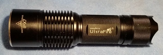
Going in this old Ultrafire. Do not need the biggest, baddest FET. I assume Rfet is needed if the Vishay is used? BTW, did ya catch the MCU? tiny25 with Bistro and a bleeder!
I reflowed my first 17 mm PD68 DD v2.1 board last night, using just one 7135. Made one mistake - thought I’d apply solder paste to the LED- pad to pre-tin it for later, but with all that solder paste on the single pad of the FET output, when the solder melted, the FET slid up to the round LED- pad and just did not want to cooperate in positioning… It was a nightmare for a while, til I could clamp down the FET and apply more hot air to re-melt the solder paste.
This was with a SIR800DP FET. Pretty sure it was my own dang fault for using too much paste on the FET output padding. The spacing for this FET though is really, really tight to the LED+ hole. Anyone else have problems or issue fitting the FET on there?
I buzzed it out and the way I positioned the FET turned out good, but kind of slanted it around the LED+ hole. Think’n bout it now, I could have sanded/grinded off the small tab on the side of the FET that is very close to the LED+ hole… Sorry, no pics available right now, though I took pics.
Haven’t tested the driver yet, but it has a ATTiny85 on it, bent pins, and will go in a ThorFire JM07 running the latest Narsil firmware (full programmable UI). The JM07 stock driver board is all prep’ed for it already (stripped, JB Weld added to support the driver mounted e-switch, switch wired to pads).
Tom, got my JM07 yesterday in the blizzard. I like it and may leave it stock, no it is not as hot as my other 26650 tube lights but I do not think it needs to be with the OP reflector. I think it will replace my hopped up C8 in the truck, in favor of runtime. It is the only light I have that will fit the RadioShack protected 26650’s I picked up, dang they are long. I just got in my first 2 SIR800DP FETs and my first 2 tiny25’s this week. I may now have to take about the D01 pill and install that FET on the board!
Tom, I know the 17mm Rev2.1 is really tight around the hole. I actually don’t like to use that board myself because of how far it pushes stuff out to the side, I mainly made it at the request of another user.
That and I’ve never had a SIR800DP , I always forget to plan for their different case shape.
Cool JM07, literally! I got my 1st one on Monday I believe, still waiting for the 2nd - tracking #'s are totally useless - both tracking #'s say left China, USPS never got them. I'm not a fan of power ON/OFF at the tail, then mode changing on the side. Narsil supports both switch's, so if I want to, I can configure mode switching w/memory on the tail and have full control on the e-switch from 1-7 modes, lock-out, battery status blinked out in voltage, etc. - all the features, plus full FET power .
Stock throw I measured was 26 kcd and 3.0 amps on a top IMR 26650 cell (EFEST). Throw is great for an OP reflector light of this size.
PD68 - actually for piggyback mounting like I’m doing, it’s not bad. I’ll probably expose more of the ground traces though for soldering to.
Actually you could wire the ground wire directly to the ground pins of the FET so nothing is lost on a thin driver trace. That, combined with the direct LED+ wiring eliminates all driver traces for power to the LED — only part the signal is going through is the FET itself.
Have you or anyone been ordering the 2 oz. copper option? I spec’d it on my last order of 20mm DD 2.1’s, be a couple of weeks before they are in.
I ordered it on a some tailcap boards, and it’s crazy thin - thin enough that I’m not sure how much to trust the strength of it on anything bigger than 17mm
I cannot imagine them being great for the tailcap boards, but I can really see a use for them in drivers. It seems that all to often the driver pockets are to shallow and the rings are hard to fit well. I am really thinking about switching to them for my next batch of drivers. I am getting low on driver boards and will be ordering soon.
 .
.