Nope no pics, the Armytech had 2 pins on the driver that were lightly soldered to the mcpcb, flush/slightly below the masking of the mcpcb, the only lead or wire was for a NTC that was on the mcpcb, most of which got destroyed getting the screw in pill out of the body. The only other wire was a secondary ground wire encapsulated in the potting on the driver.
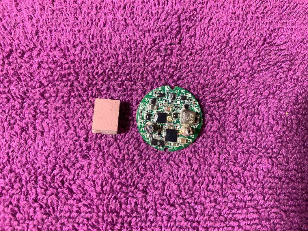
Found the SF driver….here is a couple pics…
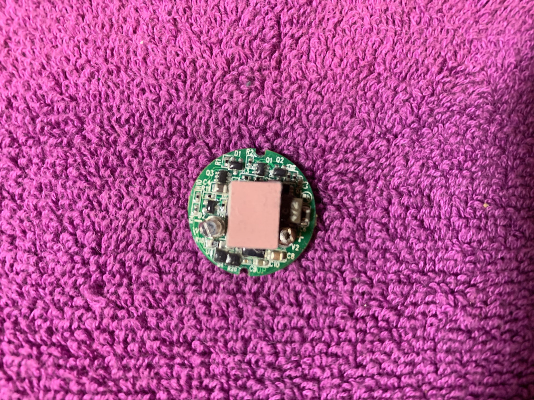
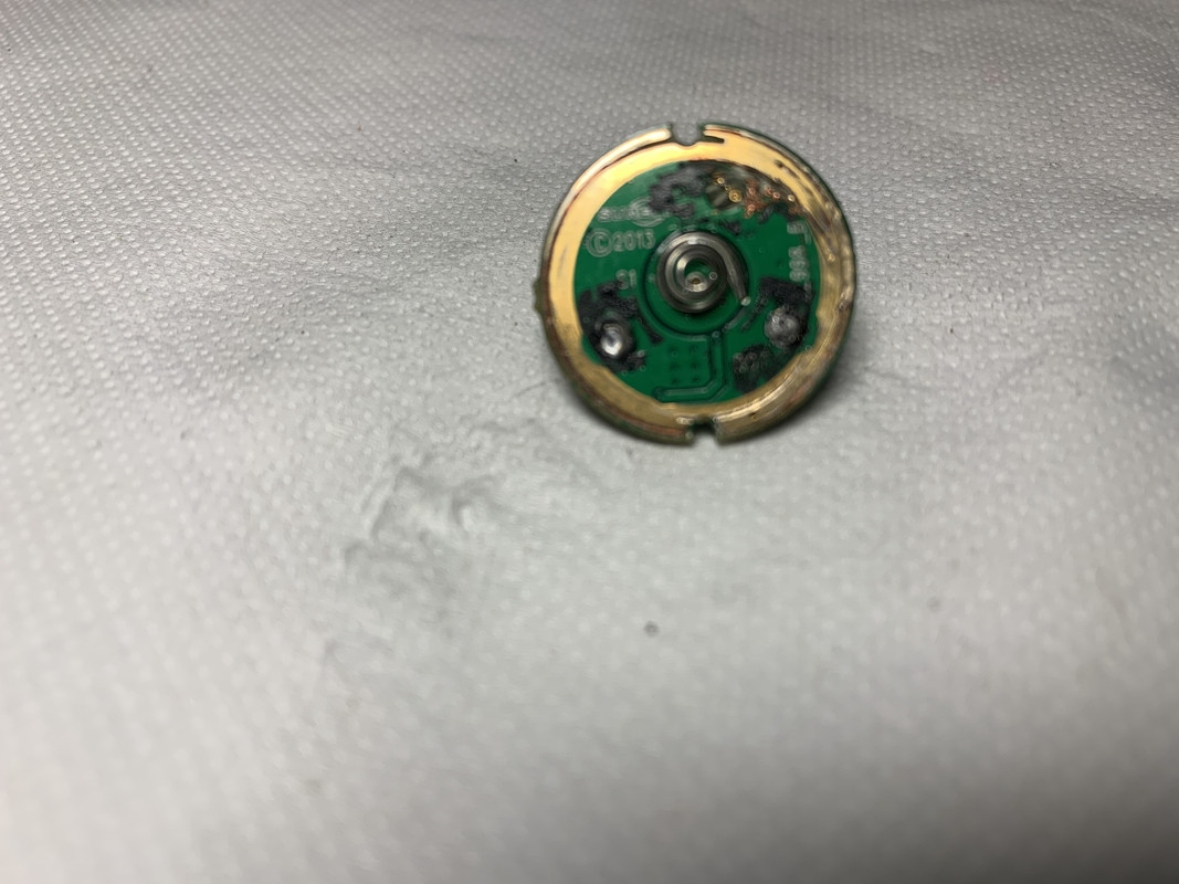
Back side shot
I may have come across something like you described in some lights like here -

and here -

(…which would go into a driver like the one Kawi pictures above.)
I believe Lexel is further proposing mechanical attachment for simple and solder-free changeout. The challenge would be secure attachment. The concept would probably be of greatest benefit to tinkers and flasholics since few muggles would actually ever changeout their emitters, and manufactures would prefer the lower expense/greater permanance of solder.
But the ideas are great and this can get exciting.
Snap in connectors like the Surefire had pins on the driver and board, I couldn’t get it apart, so I cut it.
I’m thinking about this Lexel’s idea from time to time. I would really like to see it implemented one day.
Now…I’m on the topic on making flashlights tough.
One toughness problem commonly assiciated with regular drivers is that when a light falls head-down, cell impact energy is transferred to the driver at the centrer. Then the driver transfers it to the host at the edges.
Energy transfer from the driver to the shelf would be better. And this may actually facilitate it, with 2 contact points near the centre of PCB. There’s a bit “but” though. The connectors are quite small. Their points of contant with the driver are likely small as well. This will cause localized stress on the PCB…and I’m not sure if that’s actually any better than energy transfer to the sides.
What do you think?
The Fraz at CPF has done something similar yet different - he mounts MCPCB with screws which also carry electricity, so there’s no soldered connection to the LED.
Click.
I did wonder about using something like mmcx connectors on the MCPCB, so you could just replace the LED. But not sure how well they would hold up under load.
Now that I think about it…a nut soldered to a PCB pad, a matching screw, something to prevent the PCB from rotating.
Pros:
- assembly with just a screwdriver
- presses MCPCB against the host, no need for optics or other ways to do that
- secures the driver, no need for a retaining ring
- easy to assemble even in unibody hosts
- with the right screws, very low resistance
- (? maybe ?) better thermal path to the driver (and therefore better thermal protection control)
Cons:
- Host-dependent screw length
Overall…I really like it.