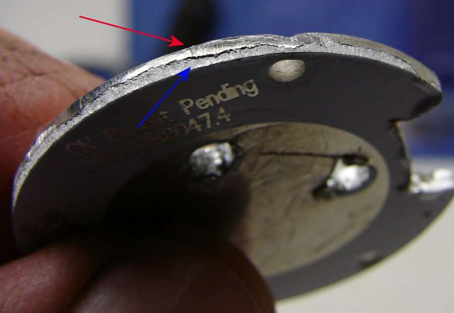
I just wanted to post a note about the edge of the heat sink board. For those who may not know, these marks appear to be common “shear and break” marks that result when the disc was stamped out of a sheet of raw material. Shear (smooth portion of the edge) is where material smears during the start of punching, and Break is where material finally fractures (rough portion of the edge). The smoothness is not likely a result of the act of pressing the disc into the flashlight body.
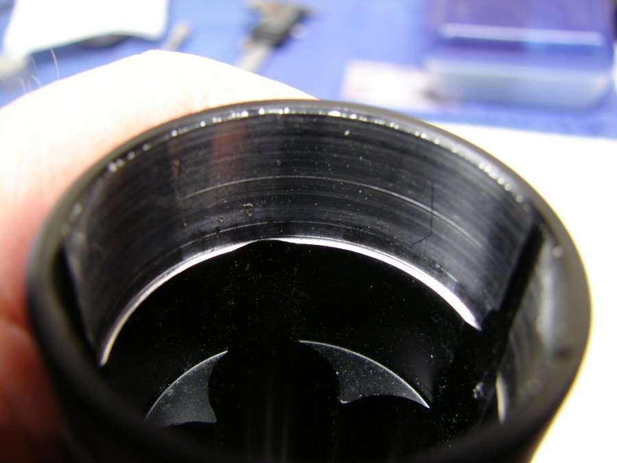
On the inside of the flashlight, there appears to be rub marks from the “shear” edge of the disc. Did it take significant force to remove the disc? If the disc came out without minimal effort, I would expect poor heat conduction path design to the body of the flashlight. However, it appears by the last photo taken that the board has hammer marks - an indication it had to be driven into position. This would greatly improve the thermal conduction path.
In addition, the disc would tend to “grow” radially due to thermal expansion and bear harder against the body wall during operation. This would be because the disc would always be hotter than the flashlight body.
In any case, accomplishing this requires very tight tolerance between the inner diameter of the flashlight and the outer diameter of the disc. I agree that it seems to make more sense to just put in a larger shelf where possible.
Generally, and interesting discussion about design and longevity. The example of Jetbeam’s lack of conduction path is something I’ve experienced many times over. At least their emitter board USUALLY touches the aluminum body of the flashlight without any glue. Anytime a bead of silicone is used for attachment and it is not aggressively squeezed out, they are inserting a very effective insulator. I have found silicone adhesive junk common in budget flashlights.
Wow! and just think they insist they are a top name brand and demand MAP because of it, just shows they’re a typical Chinese company cutting corners just like the rest of them.
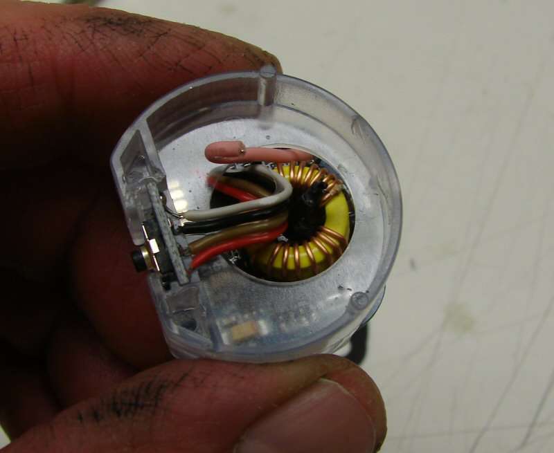
The heat sink board sits on top of the plastic housing that holds the driver and the contact board underneath. No hammering was necessary to remove everything. I just pushed on the assembly from the contact board side and it popped out. Was it tight against the body? Yes, but not that tight. Would it swell when it got hot? yes, I am sure it would. Is it sufficient? Apparently so. As I said before, it works, so most of what I believe in about heat sinks is probably misguided. It works, but I will never beileve it's the proper way to make a heat sink, just the simple and cheap way.
The plastic housing could have been a metal housing and then the heat sink board would have set on a metal housing, which would have touched the body and there would have been a much larger surface area for heat transfer. But, that would have been a lot more expensive to manufacture.