Oshpark Projects

You should make it more general purpose and break out all 16 pins… ideally to 4 x 0.1” headers that are spaced some multiple of 0.1” apart.

Do you need one? I can do that for you but I already orderd (another one I needed yesterday so had to get it ordered ASAP), otherwise I’ll go threw a couple chips trying to airwire to it if I don’t get the boards soon enough lol.

I might go ahead and do that. About the standard header pins, is that common practice to hook to breakout boards with header pin’s? I just wire to mine but I can do that while I’m at it (I have .lbr parts for 2-32pin headers lol)

Edit: so to do it correct should he center pad also have its own pin? Cause on PIC it’s electrically connected to pin 13 (VSS).

It’s just seems like a good idea if you are building a QFN breakout board to break out all the pins and 0.1” spacing headers are the standard.

Well, 4 x 4 pin headers in a box pattern does not do much good for most plugin breadboards since the vertical rows of holes are all connected together. It does make the layout easier and tidier and is useful for solder type breadboards.

The center pad on some chips wants to be left open. On other chips it needs to be connected to ground. A universal breakout board should probably have a way of connecting something to the center pad.

All good points, but I think that there is not a strong need to re-invent the wheel - aren’t perfectly good breakout boards available much more cheaply already?
http://www.ebay.com/itm/QFN16-to-DIP16-PCB-adapter-4mm-x-4mm-5pcs-/130886271445
http://www.ebay.com/itm/5-Pcs-0-5mm-to-2-54mm-LGA16-QFN16-to-DIP-Adapter-SMD-convert-/271276167123
etc

Already laid out for DIP w/ all pins broken out.

Maybe take a look at Vf? If the Vf has gone up a bit for U3 (or just that sample) that could certainly rain on the parade.

I took the liberty to make a line of boards to my latest needs and I’m quite happy with the result.
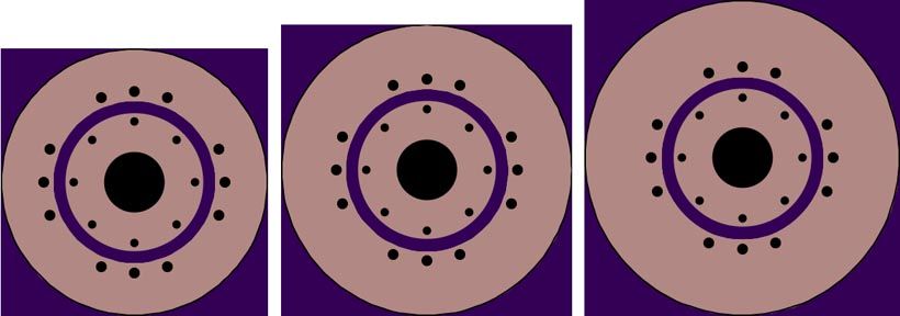
22mm contact board
24mm contact board
26mm contact board

BLF-Thread with some description and pics.

-

I truly recognize what you all are pulling together here, as I took a small peek into it.
Wight, nod from me here, thx for your assistance, more about to come.

Have you ordered any of these to verify the designs.

I think he’s ordered & verified the 22mm version, see the 4th link in his post above. While you’re there, take special note of the neatly threaded together Nanjg 105c and adapter board!

Also, just BTW, the central hole is a via. (So there is no opportunity to screw up cutouts since it’s not a cutout.)

I can't see why you couldn't put include two boards in one gerber file, but you'd probably have to get creative with how they 'join' together.

It may be a moot point though - OSHPark charge by surface area. Two boards as one file, or two files with one board in each will cost the same.

To help with layout's when the stack is critical (through need to line up etc) I create both boards in the one .sch and .brd, complete both, and then save the file twice as "name_topboard" and "name_bottomboard" (or whatever) and then delete the appropriate section of the schematic and board in each file. Just makes your workflow easier when lining things up on each board, especially if you're making it up on the fly like I tend to do ;)

I have the 22mm version here and pictured it in the linked thread. All 3 versions derive from the same brd-file, just expanded. I uploaded the brd to OSHpark so anyone can check or adapt if needed.

I’ll update the op soon. I think there may be some other things to add by CK but last I heard those were on hold.

Is anyone interested in a MOSFET switch for the L2D?

I stumbled across an L2D tear down and noticed that the switch is a very simple rectangular PCB with a normal clicky installed. Apparently the clicky is quite crap and loses the user a noticeable amount of power.

In theory it should be stupidly simple to design a new PCB that slots in place of the stock PCB, uses the stock switch but adds a MOSFET to actually turn the drop-in on and off.

A P-Channel MOSFET would be required, and a connection for ground would also be needed as P-Channel MOSFETs are turned on by connecting the MOSFET gate to ground. Here is a good tutorial. I do not own an L2D, so I'm assuming the Switch housing (which is plastic) is press fit into the collar that holds the switch boot etc. Is the inside of the collar bare metal or anodized?

If there's interest I can come up with a circuit and have it up on OSHPark tonight for people to order and experiment with. Just have to find a cheap and suitable P-Channel MOSFET first. We'd want one with a Rds (on) test voltage of between 0 and 2.7V, and a Continuous Drain current of 10A+.

I am only used to working with N-channel MOSFET, but I believe for our application the only difference is that pulling the gate pin low turns it on, not off and that the MOSFET goes between BATT+ and the drop-in, not between the drop-in and BATT-.

- Matt

PS. Only doing this because it should take no time to do (touch wood). Just in case people are wondering as I have turned down a lot of requests lately due to my busy life at the moment!

  • The L2D recently crossed my mind while thinking of potential momentary switch 1x18650 lights. Not directly related, just mentioning it.
  • The stock switch seems quite large, same size as a tailcap switch… I guess you’d need a plunger to operate a momentary switch?
  • Or would you flip the plastic holder over and drill a hole in the thin side of it instead of the thick side, so that the PCB would be closer to the switch boot?
  • Seems like what the L2D needs most is a spring bypass for the tail spring.
  • I’ve only seen this teardown image myself.

I don’t have a Solarforce L2D, so I can’t really add much to the conversation.

That's the same image I've seen :)

My idea was to just use the stock switch to keep it simple and cheap to do. A proof of concept if you will. Could then be take further if needed, though keep in mind this is a P60 host so an eSwitch is pointless. Or does the L2D have no momentary at all? It's just on or off? Bit weak if it is...

I think Solarforce lights come stock with a forward clicky which can act as a momentary switch(no) as opposed to a reverse clicky which can act as a momentary switch (nc). You undoubtedly know that but I’m just filling in the blanks for any that don’t.

Never assume I know anything lol. I just read that the L2D has no momentary functionality which I find odd as my interpretation of momentary is how you have described it. This makes the comment "no momentary" really odd. So I'm confused!

Solarforce lights can come with either a forward or reverse clicky. For tail-switches they tell you what you are purchasing. It seems that they tell you for the L2D as well and it’s a “reverse click switch” aka reverse clicky. Reverse clickies do not have momentary-on action (they can be momentarily turned off while they are already clicked on).

Just because it’s sold as a P60 host doesn’t mean that it can’t have an e-switch controlled driver in it with a momentary e-switch (what I was referring to in the top section of my post #1394 above). I don’t see that as pointless… e-switches allow for different types of input, so you can do long-press/short-press and differentiate between presses that originate when the light is on or off.

I just got in qty 6 of C_K's BLF 17dd_v3.1 boards - they look awesome! I'm having big troubles programming any of the custom boards lately - hope I can work it out with these.

Ah, no I understand you better now. You couldn't do the whole eSwitch thing with a stock P60 though? You'd lose some of the modularity I'd think. A MOSFET switch would work regardless of forward or reverse switching. I was just trying to make the idea as simple as possible to work with hence recycling parts that come with the light in standard form, adding a new PCB, MOSFET and a resistor or two and away you go.

Just a thought.

Correct, one would have to use a modified P60 or or just a copper bar style thing like some folks around here and CPF have been known to do. (You could gain back any space normally reserved for a driver pocket too.)

Yes, the MOSFET switch would work with either type of switching - I realize that. If I brought up the topic of momentary action on clicky switches I certainly didn’t intend to - it seemed like you and RBD suddenly started talking about it? I couldn’t tell if that was in response to when I said “momentary switch,” but a momentary switch is certainly not a forward or reverse clicky switch (momentary means it does not latch!).

I’m not clear on the gains from a MOSFET switch. Djozz recently did some switch testing. The results seem to indicate a worst case resistance of <0.015 ohms, but generally much better than that I think.