Ah, no I understand you better now. You couldn't do the whole eSwitch thing with a stock P60 though? You'd lose some of the modularity I'd think. A MOSFET switch would work regardless of forward or reverse switching. I was just trying to make the idea as simple as possible to work with hence recycling parts that come with the light in standard form, adding a new PCB, MOSFET and a resistor or two and away you go.
Correct, one would have to use a modified P60 or or just a copper bar style thing like some folks around here and CPF have been known to do. (You could gain back any space normally reserved for a driver pocket too.)
Yes, the MOSFET switch would work with either type of switching - I realize that. If I brought up the topic of momentary action on clicky switches I certainly didn’t intend to - it seemed like you and RBD suddenly started talking about it? I couldn’t tell if that was in response to when I said “momentary switch,” but a momentary switch is certainly not a forward or reverse clicky switch (momentary means it does not latch!).
I’m not clear on the gains from a MOSFET switch. Djozz recently did some switch testing. The results seem to indicate a worst case resistance of <0.015 ohms, but generally much better than that I think.
Yeah so you're effectively losing the ability to mix and match driver, but still retain some ability to lego the host a bit. Still worth the effort I think :)
Right, we’re on the same page now. I don’t actively swap parts around on my P60 hosts, they normally stay the same for long periods once built. The goal would be having a quality host with a normal SMD pushbutton instead of being forced to depend on a right-angle SMD switch. (Sorry I forgot to mention that, I see it as an important point.) The Solarforce lego stuff is really just a bonus from my perspective. If a person wanted to they could even use a normal 17mm driver running an e-switch firmware (such as a Nanjg 105c with STAR momentary or an led4power LD-1, both of which expose the e-switch solder point on the back of the driver). You’d leave the driver in a normal P60 and just bring out an e-switch wire(s). That’s closer to being swapable, but not still not ideal of course!
The business of being able to configure a switch for either FWD or REV operation is interesting. I’ve taken a quick look at that project of yours before but the details had slipped my mind. For me it still seems to make the most sense to bring all the inputs back to a driver and let it decide what to do with them. Granted that we must take what we can get of course!
Assuming the FET you choose can do <5mOhm, I guess that’s reducing the resistance by a factor of somewhere between 5 and 20+ depending on what switch, drive current, and particular MOSFET are being used for the comparison.
Funny, that’s exactly what I had in mind when I ordered my Solarforce L2D. I wanted to fiddle with STAR momentary. But it’s a project on hold for a while.
I can confirm the stock side switch is a simple reverse clicky, that sits between bat+ and driver. Like swapping the switch from tail to thumb. No added functionality, just breaking the connection and allowing mode change with a light press. You can use it with or without added tailswitch, with it you have 2 breaks in the cicuit. The head section takes any P60 dropin, the difference to other SF hosts is that it’s not open to the battery tube.
I saw the pictures of the switch internals as well and was slightly aghast when I saw the thin cable. My plan is to bypass the thumb-switch with a thick wire, making an efficient connection from bat+ to driver. Then using a fwd-clicky tailcap for on/off and flashes. Then change the thumb-switch to anything that can be used as momentary, be it a fwd-clicky or a real momentary switch, and connect it to tube and the appropriate star on the driver (which will need a drilled hole in the bottom part of the P60 ‘socket’).
I know the last part sounds odd, as it completely nullifies the P60 concept of swapable dropins (the driver is hardwired to the host). But when I bought the L2D I specifically aimed for a dual switch light (fwd-clicky for on/off and momentary for mode change) and there are not may hosts for this setup on the market.
So, back on topic, I’m not sure whether one would need a FET where the switch is now. But then, I have zero experience with momentary UI and I’m not sure whether I have fully understood what you are aiming at.
But if I can be of any assistance with this host lying on my desk, I will gladly provide information needed.
Well his big is the PCB in the switch? Nothing is stopping us from using a P-channel FET to make and actual driver out of the PCB...complete with MCU and momentary firmware.
Pretty big. Plenty of room if people wanted to get creative. Heck, there wouldn't even be a need for a P-Channel FET. You could get away with an N-Channel (which we already use in pretty much every other driver) if you set up the emitter in the traditional sense.
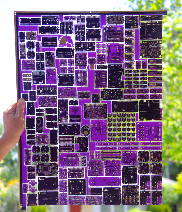
Impressive! Thanks for sharing that. I’d never have guessed…
OH SNAP! Our local college is purple and gold in their colors, the Crusaders… Their logo would look freaking awesome done on these boards! Keychains! :bigsmile: I might have to get someone to design that layout for me…
Added some stuff by CK and HQ to the op. CK, if you could start a thread for your projects I can add links. You don’t have to finalize them, that will happen as the projects get used and questions come up. Otherwise specific project questions get buried in this thread where they can be difficult to find.
I went with a different prefix so as to reduce confusion. We’ve currently got DD drivers which were created or modified by at least 3 different people using overlapping version numbering schemes and they all bear the BLFxxDD names.
Ok, I’ll post it the way you’ve written it. To anyone else: if there is a particular wording or description you want used please type it out so I can copy/paste it to the op. Thx.
I know I can connect the voltage divider before the reverse polarity diode, but to me a much cleaner design would be to connect the divider after it. I plan on using this diode as reverse polarity protection: ZLLS410TA Diodes Incorporated | Discrete Semiconductor Products | DigiKey (DigiKey part number ZLLS410TR-ND)
The specs say Vf is 0.38V. Can I count on that being accurate? Has anyone measured Vf on this particular diode? I plan on using it for a board with ATtiny13a in a 2S cell configuration (with zener diode on board).
Your link does not work for me. Post Digi-Key Part Number or use the “Short URL” button (chain links) in the upper right.
I think my position on this is well known, but here we go:
No, you cannot depend on that number. The Vf depends on the load, they may publish something in the datasheet to help you nail it down, but you still can’t depend on it IMO. Temperature will likely also cause changes [EDIT: I assume…].
0.38v sounds high to me. I was already unhappy with 0.3v from the protection diodes we’ve been using!
I don’t see why it’s cleaner. Do you mean visually cleaner or conceptually? Because the concept is definitely messier to me when you add the diode in.
A standard Zener build does not have a protection diode. I assume you’ve already accounted for this in some way?
With cleaner I mean that if the cells where inserted incorrectly, absolutely no current would sip through. The reverse polarity diode would block everything… Or so I would think.
Shouldn’t I include a protection diode in my design? My understanding of the schematics is that the zener won’t help against incorrectly inserted cells.
Edit: But if Vf over the diode is load dependent, it kind of makes the design obsolete. Didn’t know it would be, the specs specified a precise value. Thanks for the info, I’ll connect the divider before the protection diode.
Take a step back and identify what component you are concerned about damaging. Probably the MCU, right? Look at your schematic and imagine attaching a power source backwards. Now follow the path through which electricity would flow. I imagine that you’ll find that the MCU remains within spec?
There is a ‘Datasheets ZLLS410’ link on the Digikey page. Follow that and check first graph on page 4. As you can see, at least 0.1v change can occur with load. Temperature also throws a (small) monkey wrench into things, the same graph shows that. This is “good enough” in some situations, but I don’t like it and I think if you look at the datasheet you will not like it either. The datasheet will tell you what you need to know though, please do not just rely on my opinion.