Erratum: I was wrong and you were more right :-)
I wrongly integrated the intensities over the 60 deg as being half-angle rather than full apex angle.
Only ~25% of light misses the reflector. The beam/spill intensity ratio is some 30 then. Why simulations seem to have even lower ratios, I don’t know.
Which conforms to your answer, but I need to take issue with one aspect of it: the sphere you described will not be evenly illuminated to the same lux level, I believe.
This is because while the source intensity drops as the cosine of the angle, the distance must drop as the square root of the cosine of the angle to compensate for decreasing intensity and maintain the same lux illumination.
Another way of seeing it is that at say 60° the light intensity drops by half. If one drops the distance to the surface of the iso-lux bubble at this angle by two as well to compensate, the surface area illuminated by the solid angle would gets
4 times smaller and thus illumination 4 times larger, not two, which would be an overcorrection.
But adopting that change will make it harder to calculate the cap area of this ellipsoid, with for a sphere simplified things significantly and was at heart of your method. Perhaps using the circle is good enough as your answer has shown, but I don’t know how it will hold for other angles.
I actually made a very similar mistake in the other direction when I did the calculations for the first time, by forgetting to convert the 60deg spill angle to 120deg angle from center of sphere! Fortunately the numbers I got did not pass the sanity check.
I am so pleased that you brought this up! I suddenly felt uneasy with my derivations late afternoon for precisely the same reason, and I certainly need to think more carefully about it. At the moment, my hunch is that the inclination of the illuminated surface relative to the source at, say, 60deg, might correct the overcompensation, but I won’t be sure until I actually sit down and carefully do the math. I will get back to you tomorrow on this!
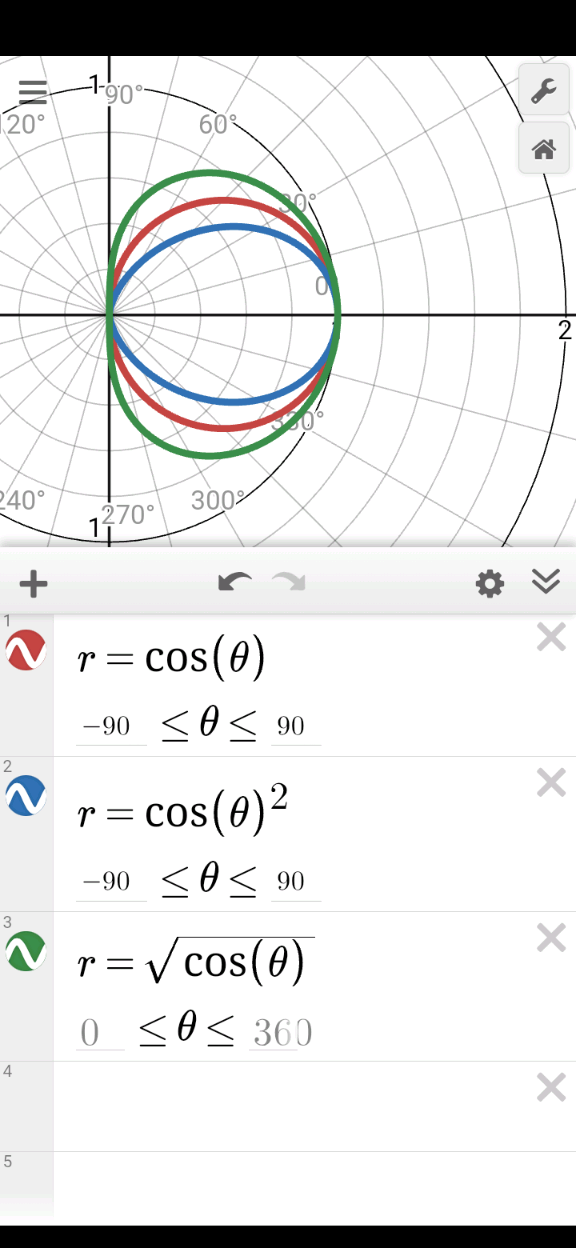
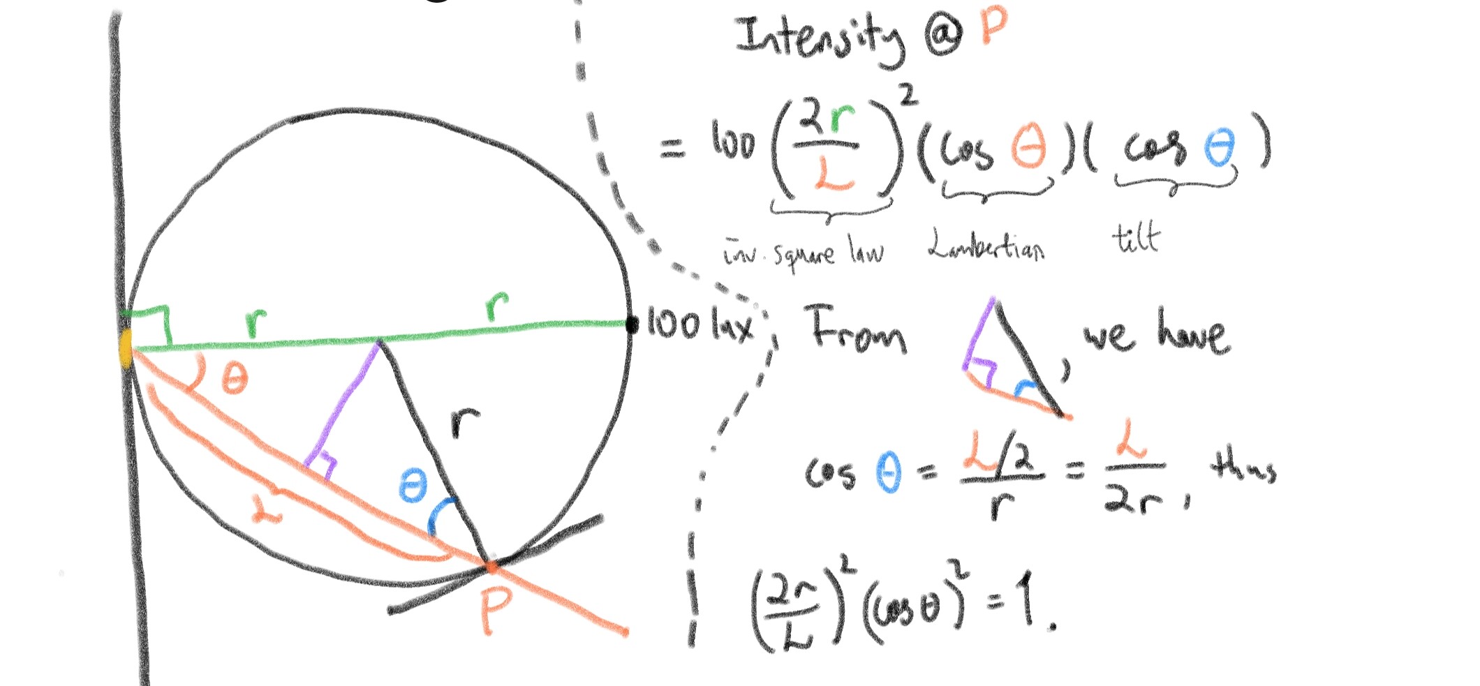
After thinking a bit more, I do believe that intensity should be constant on a sphere in front of the emitter. Attaching a janky sketch of my derivation.
Exactly my conclusion. Using a reflector light in total darkness is a jarring experience. Can’t see down your feet, and the sudden cut off to total darkness is distracting at best and sometimes down right dangerous.
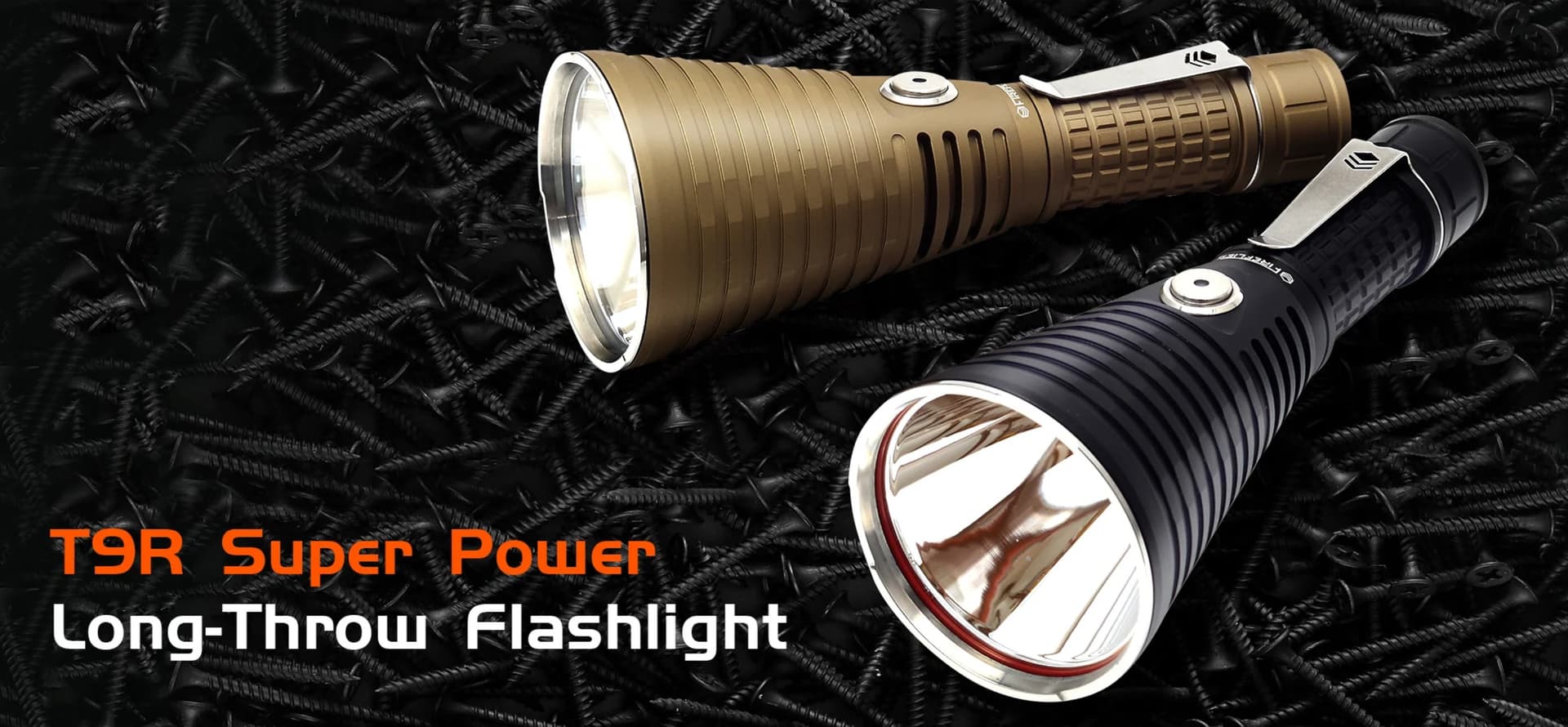
@QReciprocity42 while we are on the topic of reflector and TIR, I have a question about Depth of reflector vs Throw that I had asked you about in the past.
Does the curve below, the one at right lower hand corner, help answer the question as to how much depth is best for furthest throw? Like somewhere around 1 to 1.5 ratio of depth to width, making the reflector deeper wouldn’t help much as the curve is starting to plateau?
The curve alone does answer the question of how much depth maximizes throw, but the answer is not very useful: as deep as possible. This answer is not useful because it does not take into account the need for a wide enough spill cone to light the surroundings, which leads to another natural question: how wide should the spill cone be? “As wide as possible to light as much area as possible”, one might say. But an arbitrarily deep reflector (to maximize throw) cannot coexist with an arbitrarily wide spill cone, so you, the user, must decide what tradeoff between the two quantities works for you.
Most reflectors have a depth/diameter ratio close to 3/4 (roughly 60 degree diameter spill cone), it is common to see reflectors attaining a slightly higher or lower ratio.
EDIT: the curve, in fact, does not at all answer the question of what depth maximizes throw, because it represents the proportion of emission sent into the hotspot. This is not directly related to throw because a larger but less throwy hotspot can consist of a greater proportion of output than a smaller, more intense hotspot. However, the curve of “intensity versus aspect ratio” should still follow a similar “plateauing” trend.
I concede - correcting for the surface slant is the right thing to do and the sphere internal surface should experience constant illumination in lux everywhere.
I’m not sure about using those constant-illumination areas as being proportional to the light flux passing through them, now without slant correction, in the second part of the argument. Only the luminous flux is conserved, I think.
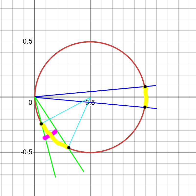
Consider this sketch. Same solid angle produce caps of different areas, depending on an angle from normal and the position of the source. It’s corrected for distance and slant when setting the shape of the equi-lumen bubble (sphere) but no longer corrected for slant when you use those areas as a proxy for equal light fluxes.
When cutting +/- 30 deg cone around the axis to estimate the portion of light going to the reflector spill, the slanting of the light-receiving surface is small, so that’s probably why the calculations still don’t need much correction when equating lux with lumens, I recon.
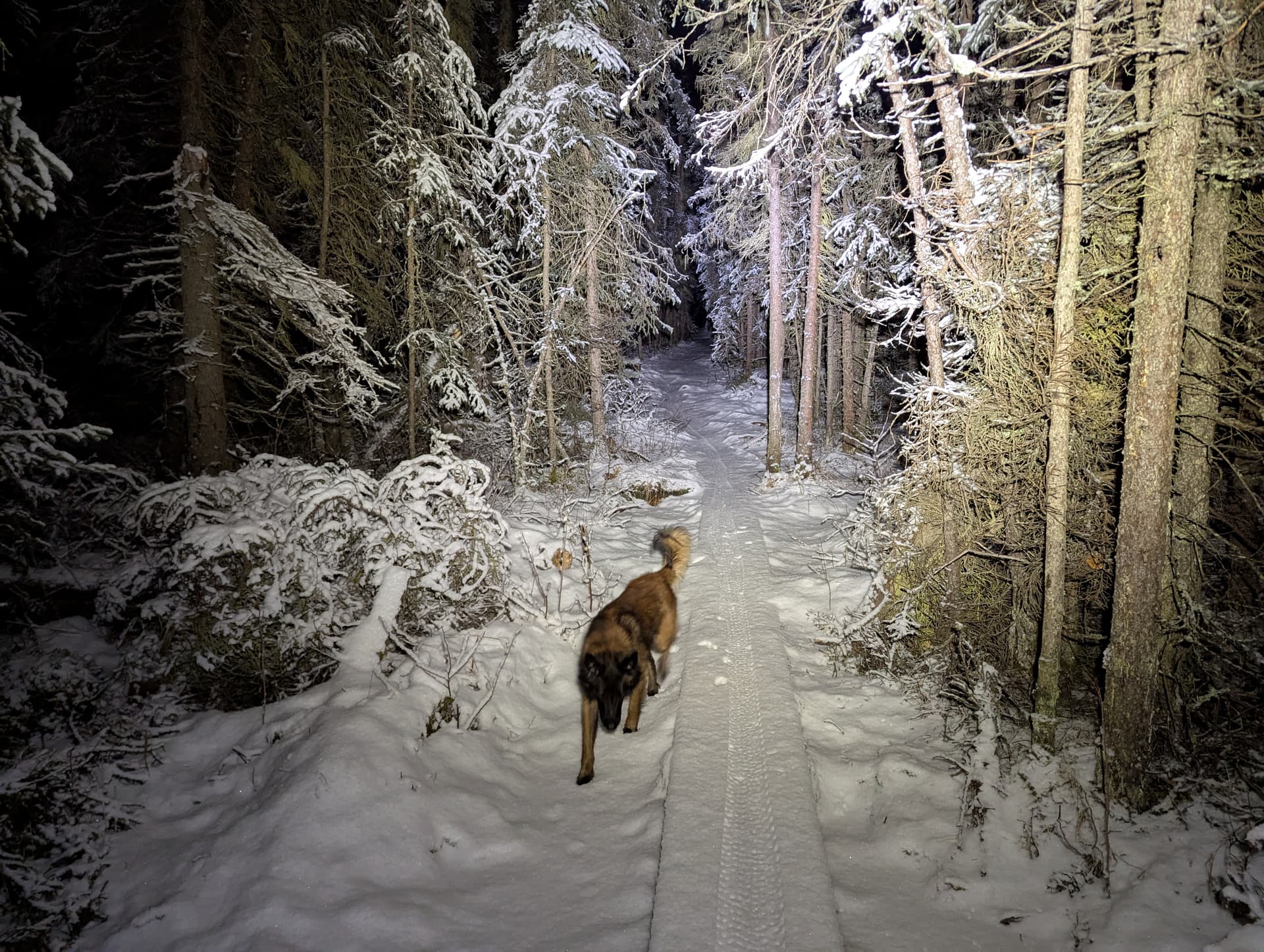
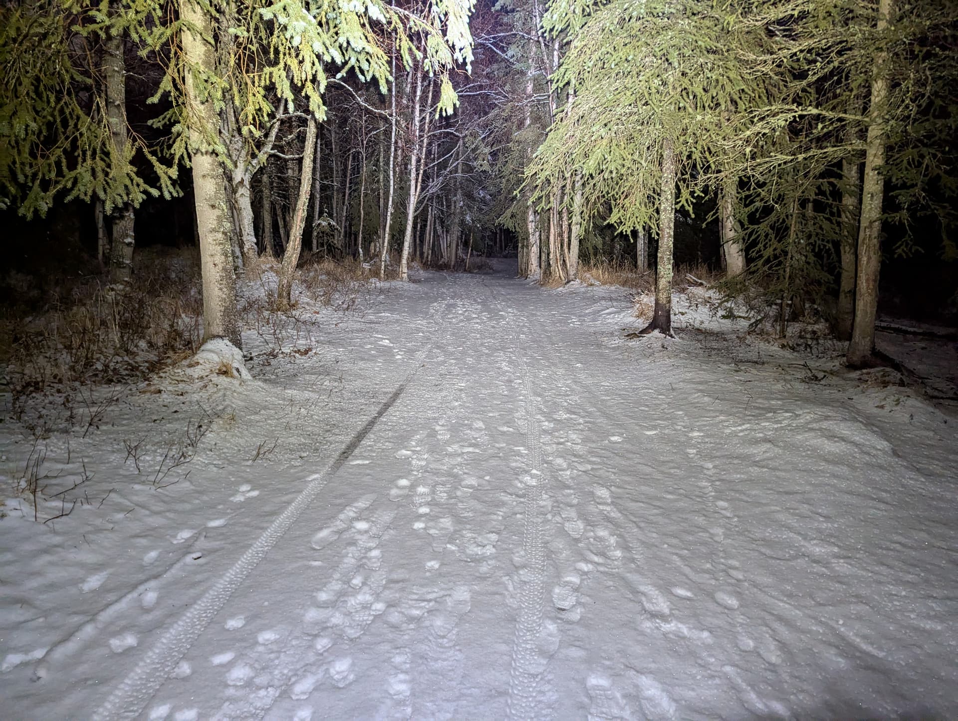
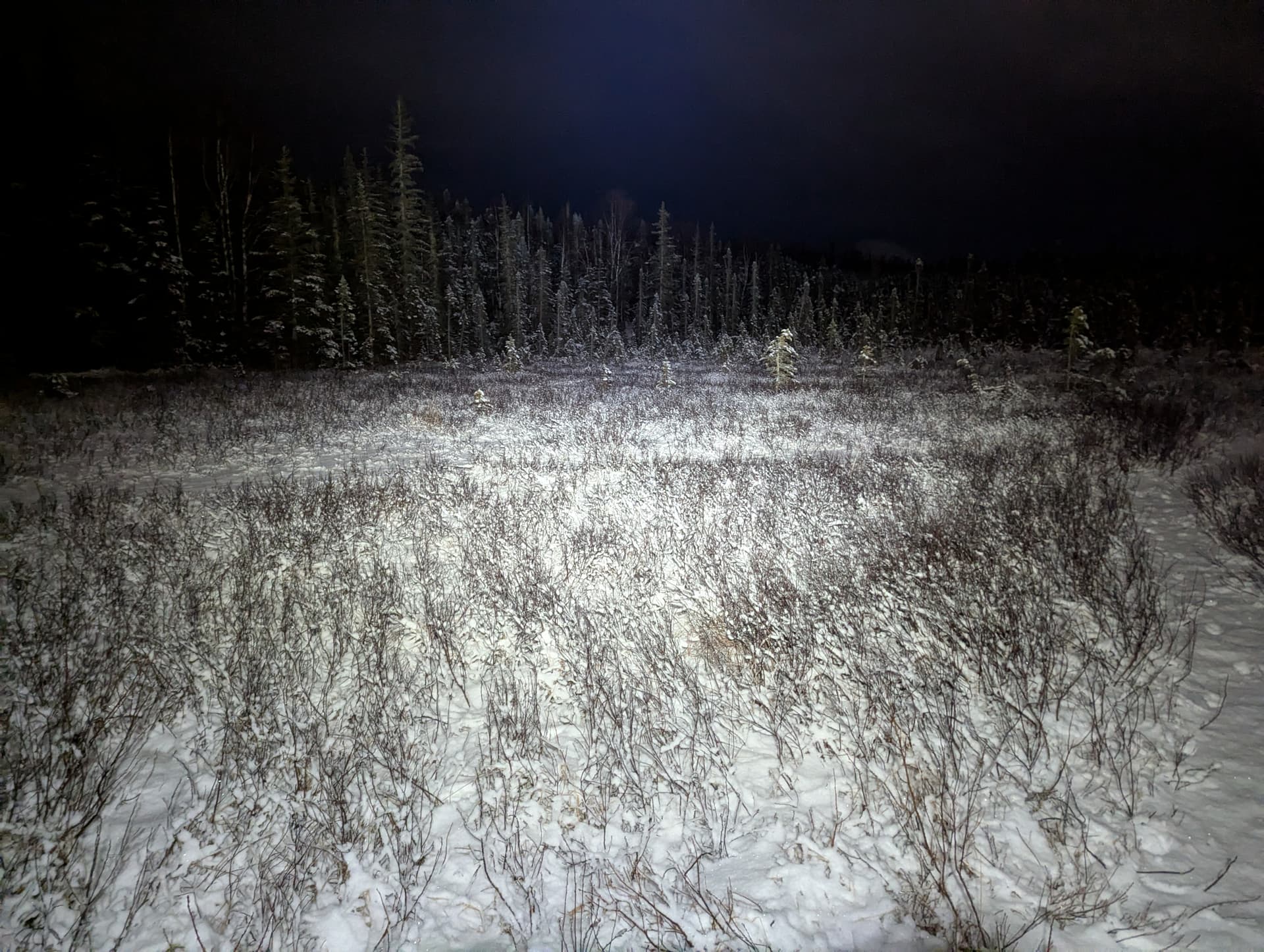
You can see the drop off in light to the left and right of the hotter spot in the background but it’s a very natural feeling view with no sharp cutoffs or sharp transitions anywhere no matter the location. It’s like making it daylight in terms of how you can run/ski/bike, navigate (as an orienteering headlamp, it should!), as well as notice wild animals like bear and moose:
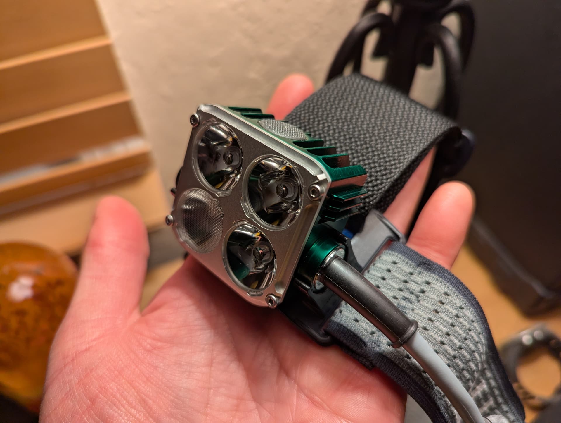
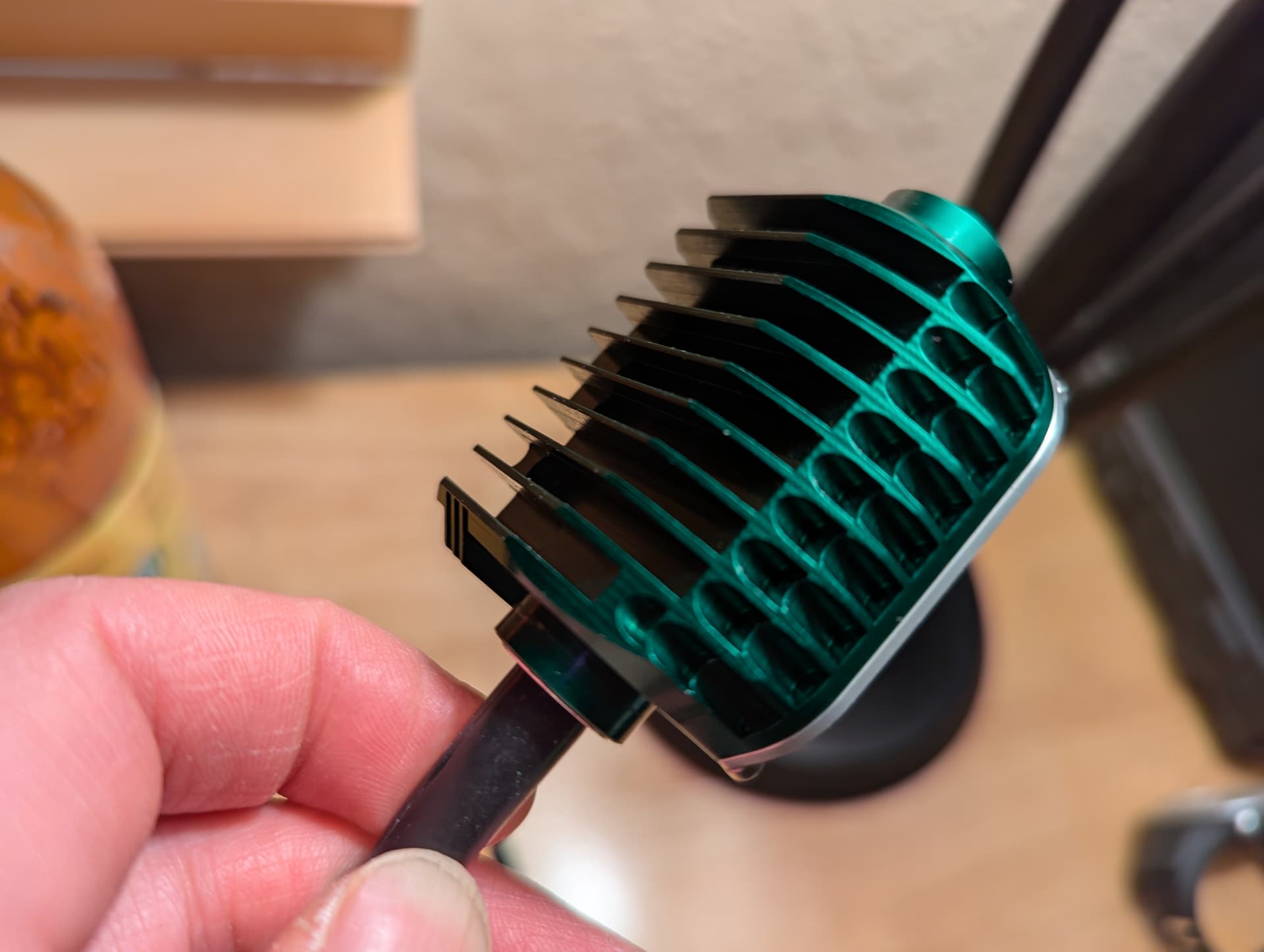
Lucifer L+. It can sustain 3500 lumens continuously with cooling from a moderately paced walk in my winter temps. I bought it mainly to use at 1800 lumens continuously, which it should do for about 3 hours (I’ve gone 2:40 without stepdown or dimming so far) with the medium-size (2x21700, 35Wh) battery pack. It might have the best luminous efficacy of any light in its weight class (332grams with headstrap and battery pack) running four W3 bin XP-L2s with a 90%+ at all levels (95-98% at some levels) efficiency driver.
Adding photos. It’s a work of art made by a major light nerd (CPF poster who posted his first prototypes there 10 years ago) who has been continuously refining his designs (including providing long warranties/seeing what fails). The headstrap beefy/comfortable and is designed for fast running/orienteering with the 2-cell battery packs on the headstrap. (The 4-cell pack is probably best worn on the body in a battery vest or pocket if running). The lighthead part is only 79g:
There is nothing to concede! We are both trying to better understand this phenomenon, and I’m simply building on your ideas.
I’m not sure if I follow–what is the distinction between “light flux” and “luminous flux”?
I’m not sure if this holds. In two dimensions, it is known that on a circle, arcs subtended by the same angle (vertex on boundary of circle) have the same length, regardless of orientation relative to the diameter. Another way to state this is: given two points P,Q on a circle and a third point V on the circle between P,Q (in either direction), varying the position of V does not change the angle PVQ. My hunch is that this should hold for arbitrary solid angles in 3D as well.
This seems harder to prove in 3D since solid angles can take many shapes (whereas in 2D, angles can be decomposed as a disjoint union of sectors). I think one can prove this for solid angles in the shape of spherical caps without too much issue by relying on symmetry, and arbitrary shapes of solid angles are probably provable by packing/approximating them with spherical caps.
In 3D, same solid angles might not subtend the same area, an interesting distinction from 2D. You’re right here.
Interesting and helpful rule-of-thumb observation. I’ll take a look at this T9R reflector when it’s here to see why it has seemingly such an odd shape.
Got it. I was concentrating on “more emission” = brighter hotspot, but forgot about the other possibility, larger hotspot.
No difference - I used it interchangeably. The point was to differentiate between flux (lm) and illumination of a surface area (lx) by this flux.
I guess what I’m trying to say is that once you established a bubble/sphere surface of constant illumination (lux), doing arithmetics on the areas of this surface as if representing the flux of the source may not hold.
If I cut a hole in this iso-lux sphere near the source optical axis and the same hole at large angle, their areas will be the same but they will ‘free’ different amounts of lights.
One way I’m trying to convince myself that this is the case is to look at the yellow and magenta arcs fore the light at large angle off axis.
If the cone has a tiny (infinitesimal) vertex angle (not to deal with unequal illumination of the slanted area due to distance differential), I can find a distance at which an area perpendicular to the cone axis will block it and have the same illumination in lux as the rest of the sphere (magenta). I can also block the same cone with slanted surface (yellow) which being part of the sphere has the same illumination by definition.
In both cases I blocked (or released) the same amount (portion of the entire flux) of light (same solid angle, at the same direction and thus intensity in cd), but the areas will be different (albeit equally illuminated).
I’ve been thinking about it some more (you know that we are both deep into the rabbit hole?).
Sticking to plane angles (I think solid angle argument will be analogous): M is the light source, and AB is the chord (and its arc) subtended by the angle AMB. The angle indeed stays constant regardless of M position as long as the A and B are fixed.
If the light source emitted constant flux in all directions, the same (2D) flux will hit the same chord/arc.
So, same flux same ‘area’? Yes, but not the same illumination in lux of this area by this flux, because of the angle of incidence corrections when calculating illumination. I think it works in reverse too: equal areas of equal illumination may not in general represent the same flux (when slanted).
TIR Optics give you much better possibility of beam control over standard reflectors when implemented well.
In my experience though, I find they are not very well implemented in most lights, and usually prefer the beam profile I get from a reflector light with DC Fix slapped in front over a TIR beam. Most TIR flashlights I have tried create a bit of a tunnel vision effect with a very dim spill which is is less practical for my uses.