Newbie question: What effect would that be likely to have? Increased amps on all modes? A bit? A lot?
ReManG wrote “The switch wires will go to the e-switch on the original board. Connect the switch wires to the contacts on the switch, it doesn’t matter which color to which side, the switch just makes the contact, no positive or negative here.”
I’m wondering about the underlined part because one side of the stock e-switch is still connected to ground. Seems like the only switch wire needed would be between pin 2 of the FET board and the non-grounded side of the e-switch?
That’s a good point. On something like an SRK it doesn’t matter what wires hook up to what. When piggybacking on a stripped driver with an integrated switch one must be more careful. The situation is as exactly as kyfishguy describes: just wire the non-GND side of the stock switch up to MCU Pin2. This is often broken out on the “OTC” pad.
Right! Thanks KyFishGuy and wight! I am no expert and was just trying to.put the idea out there for how to do this… I had not thought about the switch being connected to ground!
Whenever mine come in, I will check on this and post detailed pics…
I've done a lot of lights like this, lately installing a FET+1 driver with the Narsil programmable UI firmware running on a ATTiny85. Just posted some pics of examples here in post #16 in this JM07 here: http://budgetlightforum.com/comment/899130
I got two of these JM07's on the way, least I hope they are on the way... lol
Tom, those are some awesome mods and very fine looking work. That is exactly what I was talking about “floating” a driver, even though yours are hardwired to the bottom ex-driver…
So. Got the original driver stripped. Now just need to wait for my FET driver to arrive. Looking forward to it ![]()


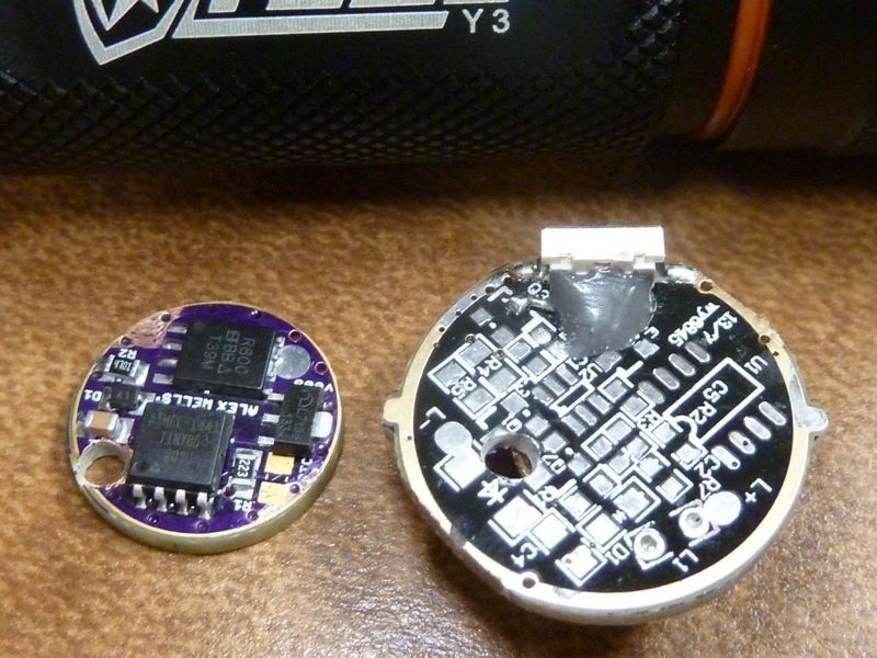
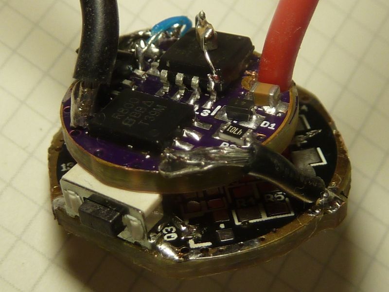
I can find several connection points for one side of the switch.
For the other side of the switch I can only find one connection pont: on single pin where there used to be a chip on the spring side.
Guess I can just use the pads on each side of the witch anyways…
The switch does not seem to have any connection to the outer ring on the driver.
Nice job, sometimes stripping a board is as aggravating as putting parts on to it…
Looking forward to your mod and getting my JM07 next week…
For stripping drivers, what I've been doing is using an iron with extra solder on the tip. This helps in hitting multiple pins, then I use SS tweezers to gently push them off the pads. After the parts are removed, I'll use solder wick to clean up the extra solder (always apply flux on the wick first), then after that, clean up with isopropyl alcohol on a paper towel. The iso. alcohol works great - everything shines up, flux stains removed, looks brand new. Also for the switch -- look it over carefully. I've had these type of PCB mounted switches bend/pushed backwards, sometimes right off the board. Your finger from operating it can apply a lot of pressure, and this type of 90 degree mount is not the most secure. At a minimum, I beef up the soldering on each side of the switch. For switch's that don't seem to have good support, I'll build a wall of support behind the switch out of JB Weld, but you must do this carefully to be sure you can still wire the switch up. I use a DMM to find a pad for the switch connection. Usually, one side of the switch is wired to ground, and the other goes to a pad of the old MCU, but you have to trace it out to be sure, and to set up your wiring. Also, I'll trace out contact pts for ground and batt+. I like to use 26 or 28 AWG wire for MCU power (low amps), and direct wire LED+ from batt+ with heavy gauge wire (20 or 18 if possible) -- prefer to drill a hole thru the old driver to allow the LED+ wire to pass thru the driver direct to the spring. For ground from the old driver to new, I try to get 3 wires to both reduce resistance and add solid support to the new driver's mount. Typically I'll use 22 AWG wires, but you can (and I have) use lots of different options, including copper strips, bare copper single strand wire, or teflon coated multi-strand wire. If using regular silicon coated wire, the length of the wires are so short, they became very stiff when soldered. You also have lots of options for getting a good ground - usually there's a ground plane covered by soldermask that can be scraped off - I use a rounded edge Exacto type of knife to do the scraping. I even will expand contact pads by scraping off surrounding soldermask, as long as there's a ground plane below it, which you can usually tell visually. Here's pics of a Yezl Y3 mod, with using JB Weld for supporting the switch:

With the JB Weld applied, this switch is rock solid now - it's not gonna budge. I did 3 Y3's this way. Again, learned the hard way - had a ZY-T11 clone light that died on me -- turned out the switch was pushed backward. Fortunately it was an easy repair because the switch itself was not damaged. I've also found these types of switch's not failing, but definitely tilted back, so would probably eventually fail, or the press needing more force to engage.
Thanks for posting Tom.
The switch and piggybacking reinforcements looks genious. That JB Weld, where do you buy that? I assume it is non conductive? Oh, and does it have any thermal capabilities?
Might have bought it on Amazon or Home Deport - can't recall. Posted on Amazon it's non-conductive by a buyer. Using JB weld is nothing unique here on BLF - actually I bought it because it's been so widely used here on mods, though don't think I've seen anyone else use it this way to support a switch. ComfyChair was the biggest proponent for it. I don't think it's a very good thermal conductor - I've used it to as such in one mod and from testing, don't think it worked well -- can't be sure though. I didn't do extensive testing nor a good scientific method. Pretty sure it doesn't make the claim to be thermal conductive. Others may have the opposite opinion though - there's been some controversy about that.
----------------------------------------------------------------------------------------
Finally got my first JM07 (2nd should be here any day). Stock #'s I got:
On a new EFEST 26650 3500 @4.19v:
3.0A at the tail w/clamp meter, lumens: 986 @start, 932 @30 secs, throw: 26.5 kcd (325 m) measured at 5 meters.
This does slightly better than specs in lumens (932 lumens vs. 910 lumens) and much better in throw (9 kcd). I'm very impressed with the quality of this light -- this was a total steal for $10. I would have gladly paid $20 for such a high quality light, specially with the quality box packing and all the spare parts included.
It's like what the F13 should have been - Give an F13 a real SS bezel, high quality anodizing, no dings or scratches, an easier to use side switch, and you got a JM07. Granted the EFEST cell I used is actually is a mis-labeled 4200 - it only has a 3500 capacity but it performs as good as a 4200 - it's about the best performing 26650 cell around - better than my Samsung 30Q's. I would not worry about the OP reflector on this light - this thing throws!! Dunno how they did it, specially with a plain glass lens (no AR).
I see there are different “versions” of the JB weld. The most common one seems to contain steel. (Which doesn’t sound good for electric isolation capabilities.)
A few google searches suggests that it is pretty insulating anyway, so maybe I’ll give it a try ![]()
Still waiting for my FET drive now…
Another thing:
Would wiring the FET driver directly to the pads which the eswitch is soldered to be any problem? (the pads in the printed “KEY” box in my pictures)
-Instead of making a hole through the old driver?
Dunno - I’d buzz it out to be sure — I always confirm with a DMM to be sure the pads I wire to will work. One side of a switch is always ground, the other is to be wired
Odd thing is, I can’t find any contact points that connects the eswitch to ground… (outer ring, right?)
Are we sure it is connected to ground and not just a pulse generating circuit interrupter? In theory it could be supplied B+ and only generates a small positive pulse when the switch is pressed. I would be surprised if it was not a simple ground contact.
-I can trace contact from the positive spring, to certain contact pads on the board, and to one side of the eswitch.
-I can trace contact from the other side of the eswitch to just one contact pad (on the opposite side of the driver board, the spring side).
-I can find no contact from any of the eswitch sides to ground.
The eswitch doesn’t seem to ground at all? Does the eswitch just short two legs on some chip?
Never had a problem tracing switches like this - done a lot. I'll start look'n at it now - pretty done with the stock measurements anyways.
Edit/Update: Ok I pulled the driver (retainer ring was tight but easy to remove with a needlenose). The switch will be easy to work with and wire up. The two backside tabs soldered down are the ones to work with. True - neither side is wired straight to ground, but that's ok. The left tab (by the 'Y' in the 'KEY' word) is directly wired to pin #6 of the MCU (spring side of driver). The other tab (by the 'K' in the 'KEY' word) is wired to a pad then to a series of resistors - no idea what the design is and doesn't matter. Once you strip off all the components, you can easily add a jumper from the 'K' side to ground, and for the 'Y' side, wire your switch pin of the newly added driver directly to this tab.
I've done these kinds of switch mods before. Sometimes you have to add extra jumpers to get to a spare pad or to a ground. If you can't find a ground pad, you may have to go direct to the outer ground ring. Sometimes you can build up ground wiring or pads yourself, sometimes you can scrape off solder mask to expose a ground plane -- all depends...
Ohh - the 'K' and 'Y' tabs could be reversed of course - whatever you find to be easier. 'K' side can go to the switch wire for the new driver, and 'Y' side can be wired to ground. All our ATTiny13A/25/45/85 MCU firmware versions want the switch input to be connected to ground when depressed, disconnected when released.
I got my JM07 in last week, it is impressive in stock form….
The modding on this one will wait a bit, the missus stole my modding extra!