Q8 modding

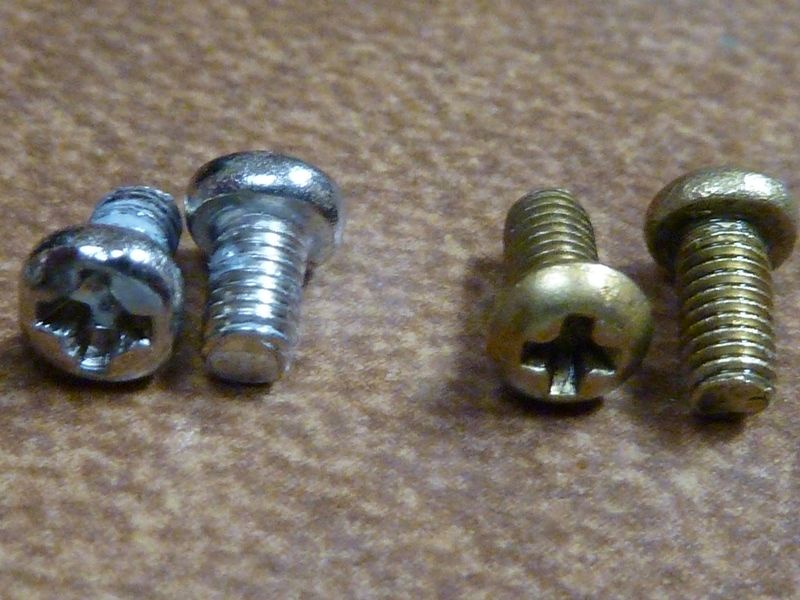
The M2.5x5mm used on the tail - worked perfect, rest of tail has the bypasses, tinning of the pads, etc., as detailed before:

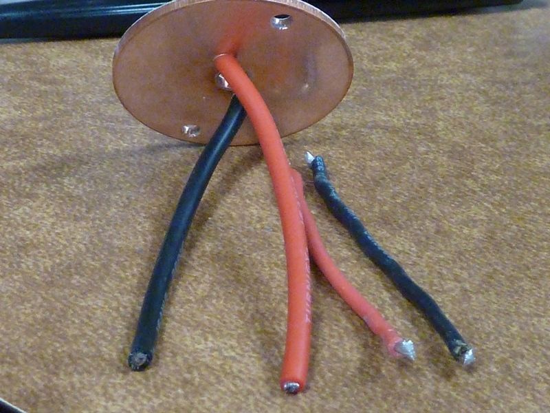
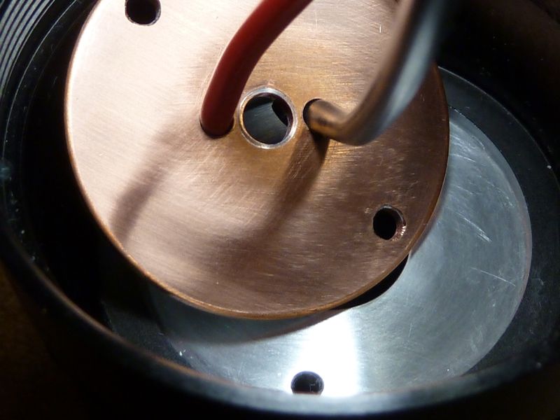
16 AWG Turnigy wire in place of the 18 AWG. Used longer length to makes it easier for driver access, stock was 62 mm, 16 AWG is 70 mm:

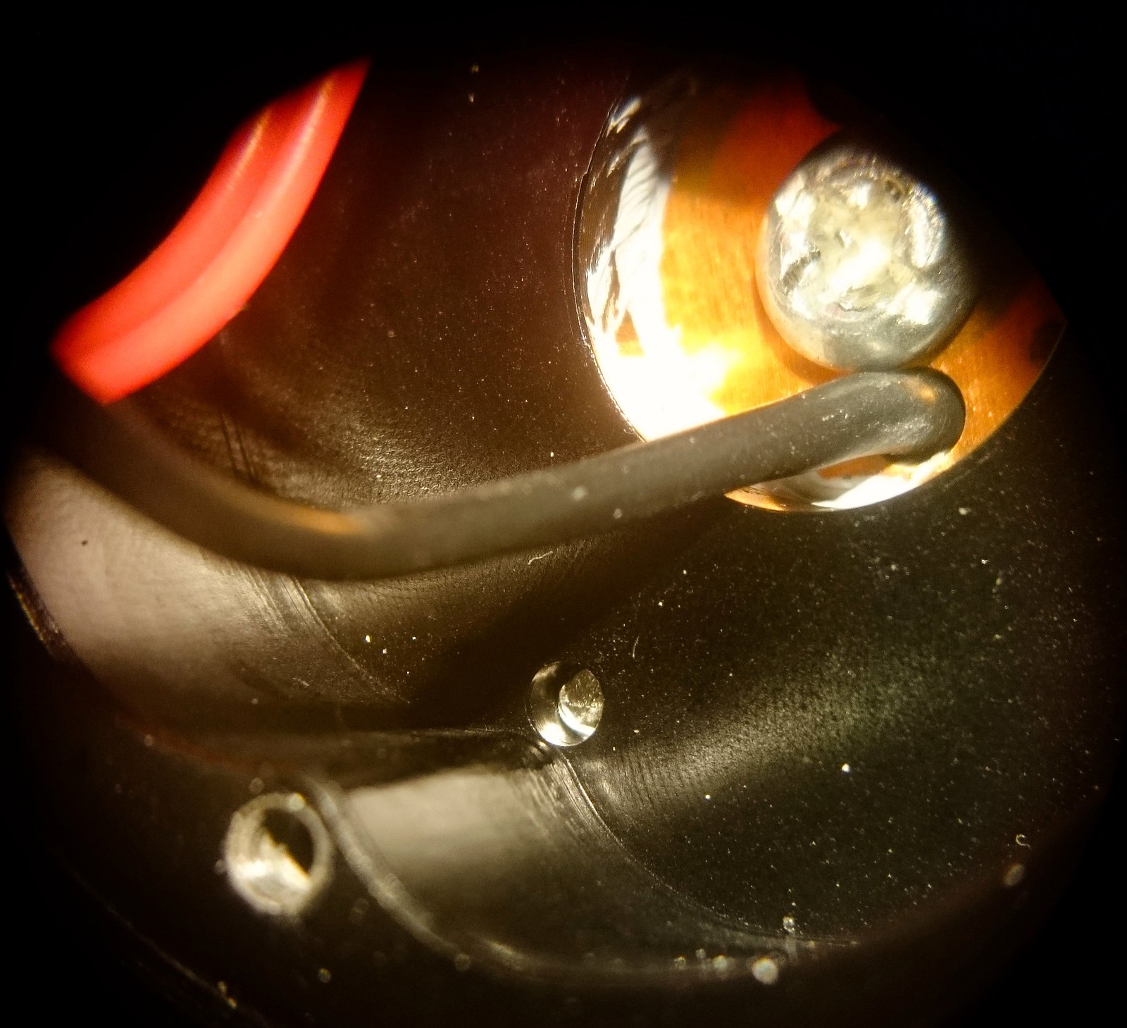
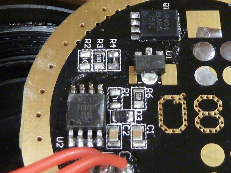
FET replaced with the reliable SIR 404DP. Notice R4 is removed and soldered over. This was from experimenting to try to get an Infineon FET to work but was unsuccessful. Ok to leave it out for now:

Sanded smooth to 2000 GRIT, both surfaces:

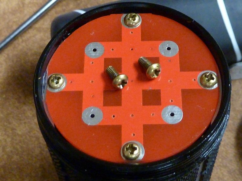
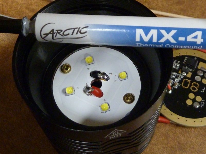
MX-4 lightly spread on shelf surface. Brass M3x6mm fit well. Stock screws are just 5mm long:

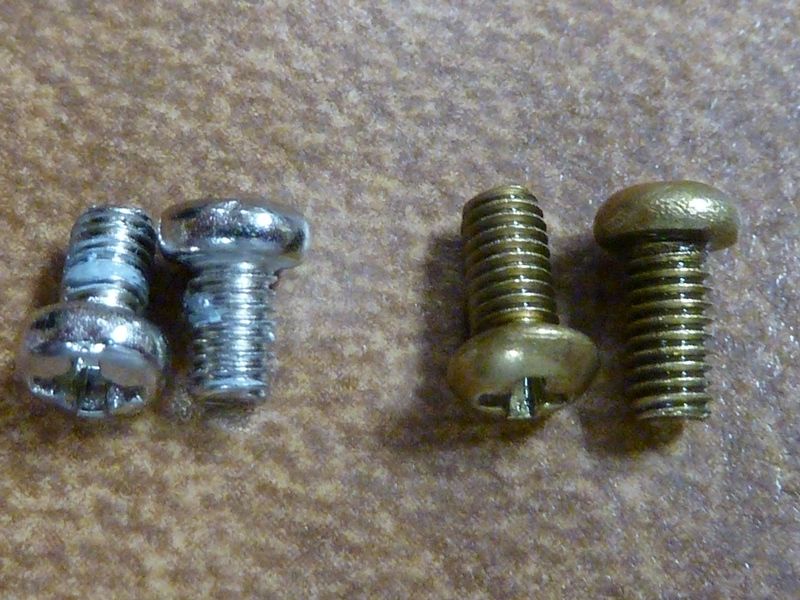
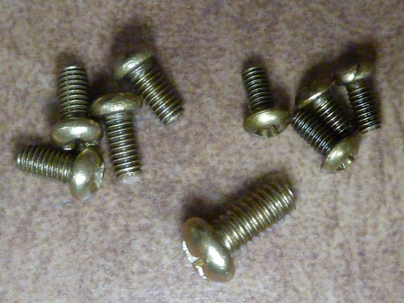
Full set of brass replacement screws, but the 2 driver screws don't fit as is - they are too long at 6 mm, stock are 5 mm, and the head heights are bout 0.4 mm higher than the brass ring. Ring is about 1.5 mm high.

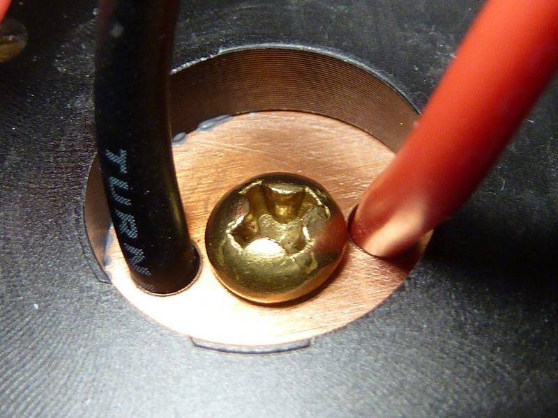
Brass M4x8mm shown here, fit well:

And the results? Well it's best #'s I've gotten on a Q8, as expected of course. Others have posted using 16 AWG and replacement FET, so I'm not the first, but maybe the first to measure the results. With 30QBT's at 4.20V:

Lumens: 7,340 @start, 6,720 @30 secs, throw: 70 kcd taken at 5m (529m)

Also fyi, I wanted to do a FET swap comparative test, so I had my baseline modded Q8 with the tail assembly mods. So on 30Q BT's at 4.19V:

Lumens: 6,900 @start, 6,500 @15 secs (shorter time to save on cells)

Then swapped the FET to a SIR404DP and using the same cells as-is:

Lumens: 7,070 @start, 6,680 @15 secs

Again on full fresh cells at 4.19V to test the FET swap:

Lumens: 7,280 @start, 6,630 @30 secs

Now this is only one test, and I vary the sets of cells used, and always think there are always many variations in measurements, so hard to come to positive conclusions on things from tests like these. But the pattern above indicates there is a small nice bump from the FET upgrade, and maybe the wire swap from 18 to 16 doesn't mean much, but again, too many variables here to conclude that. The 16 and 18 AWG Turnigy wire I have is far more flexible than the 18 AWG stock wires, so I don't know if that a plus or minus for resistance, though I find the flexible wires far easier to work with, probably less chance to rip a pad off as well.

Those brass screws I order off of eBay here: http://www.ebay.com/itm/M2-M2-5-M3-Brass-Phillips-Pan-Round-Head-Cap-Bolts-Screws

have some issues. They are not clean - threads full of oil or grease, found one M3 screw where the head is off center, and many of the M2.5's have breaks or cracks in the heads. You can see an example on the right most one above. The M4's bought at a different eBay store here look better.

Maybe about double the price is worth it, comparing equivalent sizes.

> some issues
Thanks for the warning!

Sounds like those came out of scrapped hardware as salvage for resale,
despite the claim on the sales page:

> breaks or cracks in the heads
Power tool used to remove them?

Searching eBay I see the search term “thin flat head” 2.5 x 5mm turns up some possibilities …

I took mine fully apart after seeing what Tom E was going through and I can safely say I got one of the best ones. None of my screws are stripped, they all came out with ease. The LED board is also held down firmly I can confirm my screws are holding it, but they aren’t threaded very far. The worst looking screw in mine is probably the reflector screw, but it’s a phillips/flat combination so I just used a flat screwdriver to get it out. The LED centering rings all fell out when I got the reflector out and it was a pain to get them all back on. I was surprised at how thick the glass lens is on this thing, and that o-ring before the lens. I’m just gonna leave all of those screws stock for now since they are a non-issue for me. I’m still waiting on my tail end brass screws I’ll speak on the quality of them when they arrive.

Do 3M x 6 mm brass screws fit in to replace driver stock 3M x 5 mm screws or not? Or where did you order good quality 3M x 5 mm brass screws?

Does citrus degreaser work well to clean out the screw hole threads or what else can be used for that?

No, not as-is - they are too long. You can mod them: file/grind them down of course, may want to take the head height down just a little as well.

I dunno - haven't seen them listed anywhere. For myself, I might try the eBay store I bought the M4's at, linked above, to order the M3 x 6 mm's, in the hopes the higher price means higher quality, then cut the threads all the way through the shelf with a tap and/or grind them down to 5 mm size.

No clue. I was hand rubbing with isop. alcohol but takes a lot of time.

I should also mention I've seen 3 different MCPCB retaining screw thread types in Q8's:

  • holes are fully threaded (good!)
  • holes seem to have no threads at all (really bad)
  • holes are threaded only down about 5 mm, so stock screws work but 6 mm threads will bind up before fully tightening - this can be deceptive because you think it's tight when it's not. I came across this, ground down the screw to about 5.2 mm threads with a sanding disc on a rotary tool, then they worked fine.

The variations are whacky, sloppy, insane - whatever you want to call it :FACEPALM:

> The variations

It would be fascinating to see a flow chart of their production process — how many suppliers worked
on which parts, how many employees at each subcontractor.

I’m assuming a lot of the production steps were farmed out, pieces to be made wherever they could be,
and some guy somewhere in the process was feeling rushed putting threads in those screw holes
(probably doing it with a hand tool rather than on a machine, come to think of it)

And of course with nobody doing QA, the improperly threaded parts went into the mix and later,
somebody else had to shorten screws so they’d go into the partly threaded holes. Hey, chabuduo!

I'm thinking all this changes, or could change, on round 2 - after the first 500 shipped. Hopefully we'll be seeing much more consistency.

Also for those upset bout waiting because they missed out on the first 500, well, consider yourselves lucky.

I wonder if there’s a design flaw underlying the driver screw problem.

It appears nobody sells 5mm long screws in that size, which suggests that something wasn’t planned quite right.
Maybe the shelf was specified to be one millimeter too thin to accept the 6mm screws the market has available?

Not criticizing! But looking for a lesson to learn. How far back in the process was a decision made that led to this issue?

Design flaw? It's brass screws we are looking for, not as what's shipped. Plus there's lots of things we can't find - the exact springs they used, the MCPCB they used, etc. This is all true for most name brand lights as well. There are many more resources I'm unaware of, plus the sourcing in China is way better, well better for choice, not quality. It's also very easy to get things custom made there.

I wonder if there’s a design flaw or hiccup underlying the driver screw problem.

It appears nobody sells 5mm long screws in that size, which suggests that something wasn’t planned quite right.

Maybe the shelf was specified to be one millimeter too thin to accept the 6mm screws the market has available?

Not criticizing! I’m not asking to become privy to the private design conversations that went on about the Q8.

But looking for a lesson to learn. How far back in the process was a decision made that led, eventually, to this issue?

(That’s a question often useful in air crash investigations, which often can be traced back days or weeks to some oversight that led through a chain of consequences)

There has obviously been an issue with tapping the MCPCB retaining screw holes in the shelf, well at least in the first 500.

Whilst I would have expected this to be done (consistently) by CNC, perhaps it wasn’t. If done by hand, this could account for the inconsistencies.

To be done properly, i.e. to thread all the way to the bottom of the blind hole, at least two taps would be needed, the first would have a tapered end to start it in the hole. These taps cannot fully thread all the way to the bottom of the hole. To thread it all the way down a bottoming tap would be needed as a second operation. I doubt this would actually have been used.

If only the (“plug” or “intermediate”) tap was used, the useful thread length would be significantly shorter than the depth of the hole, hence shorter screws used.

I see no reason why these holes shouldn’t penetrate all the way through the shelf, meaning just one tap would be satisfactory if driven through, and any screw length could have been used, even if they stuck out of the other side.

For the other screw holes, e.g. tail PCB, driver hold-down, the holes can be drilled much deeper, so that a plug/intermediate tap would be satisfactory, provided driven in to a decent depth.

M3x5mm is a standard screw size, readily available.

E.g. http://www.ebay.co.uk/itm/M3-3mm-SOLID-BRASS-MACHINE-SCREWS-SLOTTED-CHEESE-HEAD-BOLTS-DIN84-/201211753041?var=500405121061

Or http://www.ebay.co.uk/itm/50Pcs-M3-Phillips-Pan-Head-Brass-Cross-Recessed-Machine-Screws-/182487980717

Or Pan Head M3 Machine Screws A2 Stainless Steel Phillips Head Bolts Pozi | eBay

Or 25/100X M2M2.5M3M4 Laptop Phone Small Phillips Ultra Thin Wafer Flat Head Screw | eBay

Or http://www.ebay.co.uk/itm/M3-M4-M5-Steel-Grade-10-9-Button-Head-Socket-Screw-Allen-Bolt-Choose-Bolt-Size/290735260475

Or M3, A2 STAINLESS STEEL SOCKET CAP BUTTON COUNTERSUNK CSK HEAD BOLTS SCREWS ALLEN | eBay

etc.

One more at ebay.com that ships M3 x 5 mm brass screws

Nope, it wasn’t done by CNC. Threadings for driver screws have different depth on mine and it is the same for the battery MCPCB, all four threadings have a different depth…but as long as the Q8 is working properly, who cares ?!
Nice to know that someone earn money to do the thread tapping manually.

Aching wrists towards end of shift, twist the tap a few turns less …

In the Q8 prototype3 the screwholes for fixing the MCPCB went all the way through the shelf and were fully threaded.

I just checked one of my two first 500 lights, as can be seen from the driver cavity, the holes go fully through the shelf but the visible bit under where the screw ends shows no threads.
I’m really glad that the performance of (almost?) all Q8’s is great but I must admit that I underestimated at how many details Thorfire managed to change the production light from the production prototype. Whenever a new project with Thorfire is started, once more must be explained what a production prototype is and a way must be found to enforce that no changes are made from it that are not agreed on.

PS: Whilst I have a personal preference for brass screws at the tail PCB, for perhaps theoretical electrical conductivity advantage, all the other screws can be e.g. steel, brass is of no advantage there IMO and steel perhaps better for e.g. durability of the screwdriver slots.

I’ll be fitting brass ones on the tail of mine, but I hope the other screws will be OK as-is (second batch). A bit worried about what Tom E has seen on the MCPCB securing ones though, will take a look there as a priority once I get mine, they are rather important IMO to keep MCPCB in good thermal contact. M3 tap at the ready.

Well, I'd prefer the big reflector screw and MCPCB screws to be in brass. They have direct contact with the MCPCB which I'm sure is cranking up heat from the 20-25A from the cells. Heat conductivity of brass should also be better, though not sure if there would be any measurable difference, but in theory I would think it's gonna help: reflector screw to get heat to the reflector, MCPCB retaining screws to increase heat path to the shelf.

The driver retaining screws I believe can be anything - no electric or thermal path of any worth.