What you folks are failing to understand is that the XR-E has a narrower viewing angle and that puts more light into the beam than a like emitter putting out the same amount of lumens but with a wider viewing angle. Take an XR-E R2 and an XP-E R3 and drive them both to 200 lumens and you’ll see that the bright portion of the light has a higher lux reading on the XR-E without a reflector. Put a reflector over that emitter and what light bounces off of it is of a higher intensity than if you placed that same reflector over the XP-E even though the XP-E uses more of the reflective surface. As shown above, that extra surface will mostly contribute to the corona.
SashiX & djozz:
No, actually all parts of the reflector (that are hit by the LED light) contribute equally to throw. Take a flashlight (off!) hold it at arm’s length and point it towards you. See the yellow area? All that is the effectively used apparent reflector area I’m talking about. Luminous intensity is directly proportional to that area (inner and outer parts of it). In that nice experiment the light from the inner part seems to be all spill, but that’s wrong: spill is light that doesn’t hit the reflector at all. In both pictures you get spot and spill, but in the third picture it’s outside the picture (a small part of it can be seen in the top right corner). In the second image you see the (bigger) spot from the reflector and spill around it. It’s not as bright as the spot in the right picture since the area is smaller (and maybe the ‘dead hole’ additionally reduces the effectively used area, too).
Actually the narrower XR-E angle (and by that I mean the hard limit at about ± 60° due to that metal ring) reduces throw because it makes a bigger dead hole. That’s where the deep reflectors gain some % because they have a smaller hole.
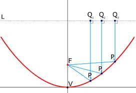
Rockspider: You drew ellipses, not parabolas. There is no way to draw two different parabolas like you did with the two ellipses to the right.
dchomak: No, it’s only the XR-E’s superior lumen density (actually luminance). That die with a different dome would throw equally (or actually a tad better).
PCC: The smaller beam angle of the XR-E works as a pre-collimator, thus the bare XR-E throws better than an otherwise equivalent XP-E. However that does NOT increase throw when using another lens or reflector to go the rest of the way to maximum collimation. XR-E's dome does not increase luminance and thus does not increase throw.
@ Dr. Jones: A few questions if I may also join this interesting Q&A thread :-)
If I understand this correctly a XP-E positioned at the same focal point in the same reflector as a XR-E should throw better due to wider beam angle that makes more light hit the reflector, right? (if lumen output of the two are equal => same drive current)
The de-doming adds to throw because
A) The apparent size (The size the reflector "sees") of the phosphorus layer becomes smaller when the led dome is removed because the led dome magnifies the phosphorous layer, right?
B) The beam angle goes from being more concentrated towards the center of the beam by the optical properties of the dome (50% of the XML intensity within the 135° of the beam if my memory serves me right) to being nearly evenly distributed in a very very wide angle (nearly 180° by the looks of it) and thus far more light hits the reflector and enters the hotspot portion of the beam. E.G the part of the beam that is "focused on infinity" because the reflector is "focused on infinity" ?
PS. Sorry if the above is difficult to read, I typed it as I thought it and my thoughts are not always linear. And TY in advance to any clarity you can add to my understanding of the matter at hand.
I know they are ellipses, but didn't have anything better than paint to draw... take the idea not the drawing.
What I meant is: There is only one parabola with a given width and height, while there are many different possible ellipse segments, as you showed.
Hey, Doc, thanks for that explanation ![]()
![]()
I will ask something that “bothers” me from my first CREE light :bigsmile: When you look exactly in the center of the reflector, you know, when your eye is centered with the led, in almost all cases you will see that yellow square of the emitter reflected. Strange, but if we take Xeno E03 with XML and Klarus P1A XPG (with a little bit wider reflector) as an example, in both cases the whole reflector will be “yellow”, but, as you will imagine, the beam patterns are quite different.
So I have a question: is there any way to tell which light (lets say similar diameter and emitter) will be more throwy or floody just looking at that LED reflection? I think that the light that reflects less “yellow” part will throw better ![]()
So, if making a cut out like the third one, produces a thrower, why not make them for lights instead of farting around with all the reflectors? Any light with a reflector could be done this way and have an instant thrower? No?
The camera settings are not standardized. :(
One possible definition of throw is the proportion light in the hotspot compared to all output (regardless of the brightness of the hotspot), in that case this is a way to increase it. But your luxreading in the hotspot will be highest when all masking is removed.
A parabola is just ellipse with one end at infinity, so technically if you just drew it big enough…
The settings could well be the same. The center is saturated in the first and last pics.
Old-Lumens:
The point of that photo was to show what contributes to what, ie first pic = second + third. So whatever’s in the middle from the second is still added to the third for the result in the first.
May I direct you to a quote from Djozz.
As others have pointed out. It’s not brighter. It’s just a smaller hotspot without spill that isn’t as bright as if there were no masking. All reflected light contributes to throw.
So then please explain to me why it is that the XR-E R2 continues to be considered the throw king when the XP-E has reached R4 binning? That’s about 10+% more output than the R2 and its still getting lower lux numbers than the older emitter.
The xr-e in ez900 form has the highest surface luminance as already mentioned. Bins are for luminance * area, so it would reason that xp-e’s have more area if what you’re saying is true.
dchomak said “However this is only true for a “point source of light” In the real world an LED only approximates a point source. The parts of the dome that are not exactly central would be out of focus, so those beams of light would not project parallel to the rest of the beam. It is because of the “out of focus” effect that XR-E LEDs make better throwers than XM-Ls. Even though there is less lumens, the smaller die size of the XR-E more closely approximates a true point source of light.”
DrJones said “dchomak: No, it’s only the XR-E’s superior lumen density (actually luminance). That die with a different dome would throw equally (or actually a tad better). ”
In real life the higher lumen density of the XR-E helps, but that is not the only reason. The following diagram is only accurate for a point source of light. A point source of light would be omnidirectional and this diagram would still be valid. In fact light emitted from the rear of the source would still make it out the front. In real life however a reflector is most efficient when light bounces off it a glancing angles (this is why a stretch of road looks “wet” off in a distance” or you can skip a rock across water) The smaller die size of the XR-E and the narrower beam (more light strikes the imperfect reflector and glancing angles) more closely resembles a point source of light and is more effective in the real world.
Now of these these effects, what contributes the most to what we experience in real life? Probably the narrower emissive angle and greater luminance of the XR-E
The EZ900 die is used in both the XR-E and the XP-E. the XP-E R4 has a higher surface brightness than the XR-E R2 and yet the XR-E R2 continually returns higher lux numbers than the XP-E in the same reflector. Please explain this.
Instead of begging the question, please show where this is evident. It’s fairly trivial to figure out what light goes where. Try tracing on a piece of paper or view the diagram above if you need convincing…
Try a Google search.