I bet designers are not trying to give us perfect “Paraboloid” reflectors, If they were then by definition, the patterns of light would be perfectly even across the beam (assuming no Optical aberrations or imperfect dimensions). setting aside the known devation from perfect of all the dead space behind an LED emitter, something else is going on.
I think all the “personality” we see. Is from two sources (or maybe controlled sides of the same coin. We know that as explained by wiki below that a “perfect” Paraboloid designed for visible light is incredibly precise and we know our light source is not a perfect “point source”. So I bet either or both are happening.
The designers are trying to give us a hot spot (because if we have shown a preference for focused light in the middle).
The the “out of focus” portions of the LED end up emphasizing uneven distributions of light aka the hot spot/corona/spill.
Artifacts are simply because of deviations from the ideal in application.
I was noticing on one of my lights that there are four distinct areas of light. Hotspot, Corona, Inner Spill, Outer Spill.
I think what we call Corona is actually the light from directly out the front, then where does the less then perfectly focused light show up? The rest of the variations I think might be from the design intent to give us hot spots and simple material deviations from ideal for the other artifacts.
The below is from good ole Wiki:
In contrast with spherical reflectors, which suffer from a spherical aberration that becomes stronger as the ratio of the beam diameter to the focal distance becomes larger, parabolic reflectors can be made to accommodate beams of any width. However, if the incoming beam makes a non-zero angle with the axis (or if the emitting point source is not placed in the focus), parabolic reflectors suffer from an aberration called coma. This is primarily of interest in telescopes because most other applications do not require sharp resolution off the axis of the parabola.
The precision to which a parabolic dish must be made in order to focus energy well depends on the wavelength of the energy. If the dish is wrong by a quarter of a wavelength, then the reflected energy will be wrong by a half wavelength, which means that it will interfere destructively with energy that has been reflected properly from another part of the dish. To prevent this, the dish must be made correctly to within about 1⁄20 of a wavelength. The wavelength range of visible light is between about 400 and 700 nanometres (nm), so in order to focus all visible light well, a reflector must be correct to within about 20 nm. For comparison, the diameter of a human hair is usually about 50,000 nm, so the required accuracy for a reflector to focus visible light is about 2500 times less than the diameter of a hair.
I think the outer spot is sometimes caused by flattening of the reflector at the back, relative to a parabola. This may be done in order to get an outer spot, or it may be done to shorten the reflector. I think I have a light that forms an outer spot this way, and the outer spot is warmer colored than the main spot or the spill, because the light hitting the back of the reflector has a longer path through the phosphor.
Yes, 20 nm. deviations from a parabola blur the spot by an amount that is comparable to the diffraction aperture limit, which is much smaller than the image of the LED.
I heard from people I was working with on an X-ray telescope that there are other possible choices of shape that handle an extended focal plane better than a parabola does, at the expense of loss of perfect point focus. Apparently, the improvement is minimal, even for a telescope, as they did not expect to pursue that line.
No, at least none of my reflectors have that. But you are right, the parts of the reflector near the LED catch the warmer light - and since they are nearer to the LED, they also cast a bigger image of the die, and these bigger images form the corona. This happens with a prefect parabola.
I can’t remember right now which it is. It isn’t the large reflector light I now have a battery in.
That is interesting about the nearer center back part of the mirror casting a larger image of the LED. I need to think that over.
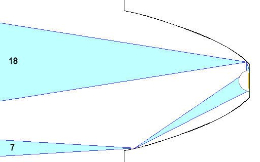
I had an illustrative idea to show. In the image below notice how deep the reflector is? It is a very, very shallow reflector. These lights throw a very tight beam a very long distance (originally built to find enemy aircraft in the sky at large distances).
So thusly a wide and shallow reflector throws the tightest beam and makes the case for the best thrower design in general. I believe the light source's location above the reflector makes no significant difference in this particular example. The light source is at the optimum focal point for a tight and long throw.
As a side note it seems that in a flashlight experiment placing the LED suspended above the parabolic reflector might be very interesting and lead to an extreme thrower if the reflector is shallow and wide.
The parabolic reflector/mirror is 60" (152.4 cm) in diameter and the searchlight has a peak output of 800,000,000 candlepower or candelas driven by a 15kW generator the light drawing 150 amps at 78 volts DC and has an effective beam visibility of 28 to 35 miles (45 to 56 km) in low humidity.
Even though the light at the edge of an LED is much smaller in area, because of the mirror’s proximity, it’s converging angles are much wider. Angle in = angle out.
That would be very useful indeed, and if that shape would be globular you would have a led shining in all directions which is great for household bulbs. But such a led is not there and that must have something to do with a more difficult or impossible production process, and perhaps also with the more difficult heatsinking of such a led.
So, who wants to join me in an experiment that costs roughly $33.00? I have found a new optic that produces a 1º beam angle with an XP-G2. Usable with XM-L2, SBT70, XHP70, whatever. All producing the absolute lowest angle of any collimation device seen to date.
Designed for throw, the XP-G2 is estimated to have a 16M hot spot at 800M. SBT70 31M at 1200M! But, this one is gonna take some creativity. It’s 157mm in diameter, 79mm depth. It has screw mount capability through it’s holder, uses a dual lens system with the large lens being of the Fresnel variety.
It’s new, and has a 20 piece MOQ. :~
I want to try this so bad! But not $660 worth of want…
Nice picture. When I was a kid, a lot of car dealers and some others had these as signs.
Since the source must be nearly isotropic, or at least a hemisphere, it seems that it would have had the same throw and wider beam with a shorter focal length mirror. So I think the very long focal length must be for practical reasons such as size and weight, cost or to be able to use a sphere as an approximation to a parabola.
Extreme thrower flashlights either are retro-reflectors, as you say, or else have lenses.
I hadn’t expected that until Dr. Jones mentioned it. That must be part of why lights with singe segment lenses form clear images of their LEDs and reflector lights don’t. With the lens convex in front, the focusing surface is about the same distance from the emitter everywhere, though that depends on the refractive index. Now it is not clear to me why reflector lights have spots with fairly sharp edges.
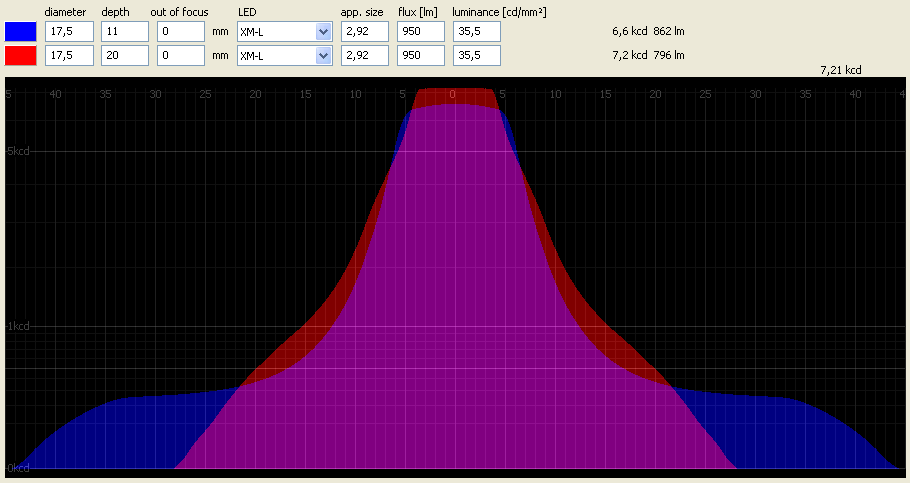
I wrote a program to simulate the beam pattern of a LED in a (SMO) paraboloid reflector, here's a screenshot for an S2+ (blue) and S2 (red) comparison.
It uses a ray tracing method and simulates about 50 million (depending on reflector size) rays to calculate the angular beam distribution.
You can see spot, corona and spill - just with a perfect parabola; for the deep S2 reflector the corona is nearly as wide as the spill.
And it shows an effect I didn't expect to be that strong: Deep reflectors reduce flux output (lumens) due to the higher fraction of reflected light and the reflexion losses (I calculated with a reflectivity of 85%).
The throw actually increases and the spot gets smaller with larger depth, that is to say shorter focal length. The opposite of what one would expect from first order and what actually happens with lenses. Also the spot and spill nearly merge into each other.
Am I understanding what you calculated?
Why doesn’t the limit of the luminance times the aperture make them both throw the same? Is that from the more efficient reflection at lower angles?
It's due to the bigger 'dead hole' for shallow reflectors, i.e. the bigger diameter of the part of the parabola that would be behind the LED and is of course omitted. The longer the focal length, the bigger the dead hole.
We have a lot of road construction in our area and the skies are virtually always filled with dust. I find it very interesting to shine a light up into the night sky with all this dust present, it clearly shows the spill, corona and hot spot area as it penetrates into the night.
I have 80 lights. 10 MT-G2, various assorted XM-L2 and XP-L and a few XP-G2, including de-domed and throwers. Shining these up into the night sky, the visible beam pattern is very interesting to see and I don’t believe any of my lights produce light in a pattern consistent with what the above graph/chart shows. Sorry, but in the real world I just haven’t seen that effect. Deep narrow reflectors put light out in a narrow cone, with the center “V” being more sharply defined as the hot spot. Lights like the Solarforce Skyline I, MaxToch SN6X-2X, and others that aren’t as deep but have close to a 1:1 ratio. Lights like the big Solarforce S2200 MT-G2 make a huge cone of a beam profile, as do the short/comparitively wide K3 and the floody triples.
There is no best ratio. Take any given size reflector and add a little more length to it and it’ll have more throw. Add a little more and more throw will be gained. As long as you add length without changing what you originally started with, it can only get better. The longer it gets, the less you stand to gain but you will keep gaining. Obviously, there’s a point where it becomes an impractical size for a flashlight and the gains aren’t worth it.
I think the quote below was intending that one end change and the other end stay fixed.
“As long as you add length without changing what you originally started with,” Which brings up the point about how to judge the “best place” for the emitter in relation to the rear of the reflector.
How do we know if we have the emitter focused correctly? Do we just cut off the reflector 1/2 an emitter height longer then the optimal focal point? (assuming we are using domed emitters)