reverse polarity protection?

Maximum reverse voltage for an LED is about 5V, so a linear driver using one Li-Ion cell will never exceed that and you don’t have to protect the LED from reverse polarity. If all you have to protect is an MCU drawing 1mA, the diode voltage drop isn’t usually a problem and the diode is simpler to implement.

FETs come in for more complex cases, like drivers that use series Li-Ion cells or have to have reverse polarity protection for a boost and / or buck converter.

Thank you kennybobby, icpart, Phlogiston. Now I understand it much better. :slight_smile:
Can anyone confirm or deny that a diode actually lowers voltage on the main FET gate please?

Confirmed, at least if FET gate is directly controlled from a MCU pin. If you turn a pin high (on) the output voltage on that pin will be the same as the MCU power voltage. So, if there is a diode between battery+ and MCU power there will be a small voltage drop over the diode.

Edit: My answer is only relevant for N-channel FET drivers, the more commonly used here. If your interest is in P-channel FET drivers, then the diode is not an issue because P-channel FETs are turned fully on when the gate is connected to GND.

I see, thank you. :slight_smile:

with kind regaurds, ermm google is not your friend, really isnt, when your fresh in and some one starts handing out encrypted answers that can only be construed as an in house joke on the question asker, it dont help, to finish them off hand them the ‘schematic’ that ‘represents’ a circuit…the very circuit that isnt quite like the schematic because the schematic is in a short hand you have learn, not only that but theres several versions of the shorthand…as a beginner yu fubar’ed before you start.(hell…the manufacturers data sheet even gives you the ‘ideal equation’ tut. fu yu impleton…hmm yes ’the ideal op op amp…now do the math? oh yeah you dont have the degree do you? ner ner nu ner ner…hmmm? this is how comes across when you dont know.(and its why yu dont know).

now add the maths in ‘as everbody already knows ’f’ over the delta of rainbow up yu bum is the derivative of misunderstanding some one purposely to miss out what Q is…as you could not work the other variables because theyre not known you’d be the genius of the century if you could actually work out exactly which of the two unknown variables they actually were and not just the infinite amount of possibilities’ which of course equals? (apart from expecting a total newbie to instantly recognise nobel prize leval maths/theories the universe and everything not no ones done before)

answer = we not telling you.

du dahh…it’s an insult to some ones intelligence(respectfully…but ehh…when yu dont know telling them on a basis of everybody else already naturally knows is bullying m8…).

this was a ‘posative feedback’ and not a personality assassination attempt btw…lol…sy…but ehh…it’s a two year cycle to catch up to the early stages of electronic competencies. Often thwart with insult after insult after power crazed moran sending yu the wrong way at every opportunity.(thats the really difficult bit…psychically predicting yet another second guess.)

thats how it feels asking a question on a forum. thats why most just dont bother asking…sheesh in electronics if you read the name it NEVER does what it sounds like does it? lol…

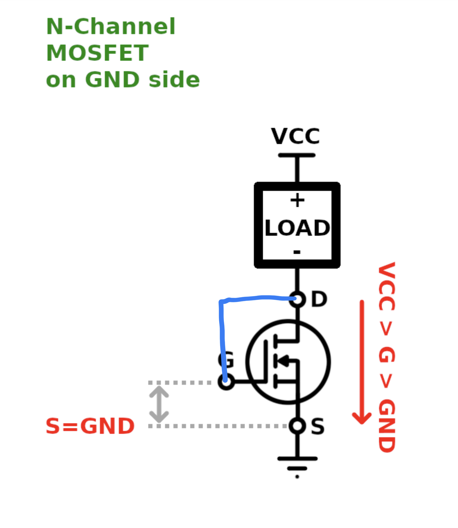
i mean? what would happen if some one drew a diagram in ‘paint’ posted it up…theres the answer…?? would it really hurt? just asking like…

lovly piccy btw…answered everything lol. (hu?).

who’s got the balls to accurately explain what n why a voltage divider, then carry it through to op ops etc, or even point out a series of varients of the same transistor circuits that get called 15 different things as you change the ware abouts of the very same components? i.e. nar its a saw tooth signal lol…hu? i thought i was filtering it?? lol…it’s bigger than yu think, and gets way too complex way to fast when bits of info are missing, and yu getting flack cuz you the dumb arse…ehhhh what ever, i havnt got the teaching skills to do it…

disclaimer; no budgies were hurt or promoted, nor received payments for this ‘try and point it out’ peace.( i just probably got extro-cav-aited outa the convo over it though…)

I coincidentally happened to be looking at this exact topic. I’d like to implement RPP for the entire driver at the tailcap and a Schottky diode simply isn’t ideal since most of them drop 0.5V when 4A passes through them.

I was thinking of using a mosfet but I’ve come to the conclusion that it’s not possible for a mosfet to activate itself and allow for reverse polarity protection at a standard tail cap without being powered by an external source or somehow getting power in parallel with the driver.

Is my understanding correct?

I originally wanted to do this but then realized the diode inside the mosfet would pass current directly through if the battery were oriented the wrong way :frowning:

Is it possible to use a tailcap mosfet for RPP without powering it with an external source?

A depletion mode fet could maybe be possible but they see, super expensive and uncommon on digikey so it’s likely not worth even exploring that avenue.

My knowledge of electronics is not very good so I’ll be doing some extensive reading to learn. It would be helpful in the meantime to know if I’m heading into a dead end trying to implement RPP in the tailcap with a mosfet without external power.

Edit: it appears this last bit is impossible.

i dont know enough to give a definitive answer but any circuit with a transistor conducts when switched on if the bias is in the right place (or gate voltage), i’m thinking as long as the negative and positive are connected…the voltage/current will flow.(and if the polarity is the wrong way…it shouldnt flow). mosfets have a capacitance which sometimes needs addressing because some times theyre used like a latching switch, as in once activated at the gate theyre own ‘self capacitance’ keeps the gate charged.
also diodes can be used they other way round so…hopefully one of the guys who knows can say how…not as simple as it looks is it…till yu know.

This article is full of mistakes. It is confusing me since it is contradictory to every single datasheet I’ve come across with the orientation of the D/S and internal diode.

This video explained it nicely and is consistent with what Infineon’s datasheet about rpp for cars says.

Hello Everyone. I’m very new to the flashlight scene. so I am not sure,
Is reverse polarity protection, What protects against you blowing up your light or battery carrier if you put your batteries in backwards? Since I have done both of those things I would like to know. If this is a silly question please bare with me,like I said I’m very new to all of this. Thanks Jim

Yum. It stops flashlight MCUs from dying when you insert the battery in the wrong way, and stops some other drivers from melting down

I have had couple of issues with Mateminco lights. First my mt18s I put batteries in backwards in one slot. The springs on that side blew right off. On my Mateminco mt70 plus I did the same thing just putting one battery backwards in the carrier and before I could get it out the springs and buttons blew off. When I questioned Mateminco customer service I was told that they removed the plastic disc that prevented this from happening, because customers were complaining that the disc’s were scratching the battery wraps. Luckily Mateminco sent me the replacement parts quickly and for very little money. Is there somewhere I could purchase those disc’s from. Mateminco and Astrolux do not carry them anymore.

I don’t think so. They also only work with button top batteries.

That’s what I use

Yes and here is why.

With either a P-type on the B+ side, or N-type on the B- side, a small parallel external wire is needed to connect the Gate to the opposite battery pole. In both cases the body diode is aligned in the normal direction of current flow and blocks reverse polarity current.

The diode will not be conducting in the forward direction when the FET is ON.

The current thru the FETs will be in an opposite direction to their typical datasheet application but it doesn’t matter; once the channel is gated open, then current can flow in either direction.

Hey guys, I’m also trying to learn about this topic, I read this article Reverse Polarity Protection

The article says to use a P-Channel Mosfet + a 100K Ohms Resistor + a Zener Diode, like in the following image that I took from their website and made it some changes:

It also says that if the Voltage Supply is less than Gate-To-Source Voltage (Vgs), we could use only the mosfet without the Resistor and Zener Diode.

Battery V+ goes to Drain - Source goes to Load - Gate goes to GND through a Resistor and Zener diode is placed between Gate and Source.

The Picture above shows 2 examples, to be applied in a flashlight driver with 1s, we need the example on the left, right? ’cuz Battery is <= 4.2V and Vgs = 2.5V.
am I right or didn’t I understand?

@Josh V, in this specific scenario, both circuits are good.

You want a zener+R to prevent the VGS to exceed what the transistor can handle. With the P-Channel MOSFET you linked, the maximum VGS it supports is +/-25V, so either circuit would be fine :slight_smile:

i found a couple of datasheets that show the CJ2301 has an internal body diode (not shown on your diagram).

Also the Vgs was listed as +/- 8V with Vds of –20V.

Not sure about the Vgs of 2.5 and +/-25 V values, maybe typos?

Hey BlueSwordM thanks for your answer, is really cool to know that both circuits works, specially if not requires resistor and zener diode due to few space on drivers.

Hey kennybobby, I bought some CJ2301’s and I have only used them in normal mode to drive a led with 3V at the gate and they work, haven’t used them as a reverse polarity protection, maybe the 2.5Vgs is relevant for normal mode and not for reverse polarity protection?

Can someone explain it, please?

About the body diode, the picture of the diagram is not showing the CJ2301’s diagram, is a picture I took from a site and I edited it.