Your post was awhile ago so slightly late response here. Might have already got answers elsewhere.
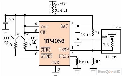
“Breaking in” wouldn’t increase termination voltage. Charger chips have a ± 1-1.5% termination accuracy, they are consistent with their termination voltage tho. Your pics show its a tp4056, ± 1.5% accuracy (4.137-4.263v) listed in its datasheet
Interestingly the ML-102 is suppose to have double tp4057 not a single tp4056. With one tp4056 the 1200mA output FT lists is wrong since the chip only claims 1000mA max and HKJ’s sample did only 850mA.
If you wanted to you could replace your chip with one that gets its termination closer to 4.2v. I don’t know if a lot of people would call it “something simple I can change on the PCB” but you do have a hot air station. :bigsmile: You can get tp4056 chips on ebay. £1 for a tp4056 charger board that you can test before transferring the chip.
Your Sanyo 2600s won’t be unhappy or harmed by 4.14v. You just miss a little bit of capacity. Not much I believe.
Thanks, Helios! I did see on Intl-Outdoor there was a ± 1% accuracy. My second ML-102 v5 terminates at 4.2V so I’m mostly using this but I may mod the other. Like the first one it also has two springs, and a single TP4056.
Yea, I was originally going to post that your tp4056 seems out of the range at 4.14v. :~
This other “tp4056” datasheet here from “Tapower Semiconductor” lists a 1% accuracy but the NanJing Top Power ASIC Corp. datasheet (1.5%) shows the logo found on actual tp4056 chips I’ve seen.
HKJ also goes with 1.5% as he mention the datasheet saying 4.137 - 4.263v
~ edit ~
Did you get yours from Intl-Outdoor? I didn’t realize their ML-102 was also labeled v5. It seems like just FT is wrong with their v5 “double tp4057”, 1200mA specs. Intl-Outdoor lists the correct 850-900mA charging current.
I charged a trustfire 18650 battery in my ml102 and wanted to try to charge my iphone from it. the iphone wouldn’t charge. i tried to use it to charge other USB devices and nothing worked. The battery seemed to be charging fine. Any ideas?
Does the light turn blue when you plug in devices to the USB charging port? Can you measure the cell voltage, check it is not below 2.9-3V? If there is no blue light at all, not even a dim blue light, maybe the cell is too low to charge anything. Do you have any other cells to test in the charger?
I have two of the ml102 chargers, and the other one works fine. nothing happens at all when I plug in a usb device. I have a usb voltage test that usually will turn on when i plug it into a port, but nothing happens when i plug it into the usb out on the bad ml102
Ive had it about a year or so but I’ve only used it a couple of times to charge a battery and havent tried to power anything until yesterday. Whats the best way to crack the case? I;m going to contact intl outdoor and see if they can do anything, and if not Ill poke around inside and see whats going on
I got 10 of the V5 to give away with gift torches for Christmas.
Tested them all, using the same battery, discharging it to about 4.00 volts in a flashlight before recharging, and found that resting voltages varied from 4.15 to 4.23 volts.
Also tried one charger three times and found it was consistent at 4.18.
p.s. The torches were all WF-504B hosts with homemade P60 dropins - XP-G2 R5 and 4x7135 KD V2 drivers and I used laptop pulls with them. I pointed out the batteries were recycled and asked everyone to look out for dud laptop batteries for me to recycle.
Something to keep in mind for this series of chargers, my ML-102 V5 charges to 4.1V and a replacement ML-101 V5.1 charges to 4.04V, both are latest version, so keep in mind your likely to get the same if you buy today.
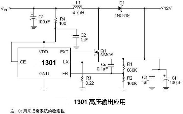
It appears the voltage divider circuit on the PT1301 is capable of providing different output voltages from 3.3 all the way up to 12vdc
If you notice on the FB pin of the PT1301, the associated resistor voltage divider bridge…that controls the output voltage that is tied to the USB output port
And by looking at the bottom photo of the V5, it appears they have two 300mA PT1301’s (U2 and U3) working in parallel to provide the 500+ mA output current (makes you wonder if they are stackable??)
And on the top side where the TP4056 (U1) is located (I don’t see it in the FT image) there is probably an output current limiting resistor on pin 2 of the IC (R2/RProg/pin2), changing the 122 resistor (R2) 1.2K (from 1A) to a 222 2.2K (500mA) charge this might solve the overheat of the battery on charge…1A into a single cell is high…Li Ion’s chemistry is best with low to moderate charge and then the ability to dump said charge VERY fast (In case you were wondering these are the EXACT same type of Li Ion charge boards you can get that have the TP4056 chipset http://www.fasttech.com/products/0/10005926/1585501-tp4056-1a-li-ion-battery-charging-module
It also appears as there is a solder point to put a USB micro connector right next to the USB mini…with a slight bit of modification of course [adding another diode, the same as D1 connected to the USB mini plug circuitry, and gently cutting a hole in the side of the housing]
The U1301 is a boost regulator, this means that it will always increase the voltage, i.e. with 4 volt on the LiIon battery, you cannot get 3.3 volt out.
I also doubt there are two U1301, one U1301 and a transistor is more likely, especially with only one inductor.