I did videos on the first two, check out my YT channel in my sig. The Xiaomi charger is the same as a ZMI.
And at the moment I'm making a video about the QB815, the 15.000mAh version of that powerbank.
thanks I’ll watch them
I saw the DTU-CCL01 (USB load tester, similar to ZL1100) mentioned by Angerdan here (and AliExpress is now having a sale till Aug 30, so prices may be 1-3 dollars cheaper for the next few days)

(it seems to be in Russian)

official website appears to be here (webpage for the DTU-CCL01:
http://d-tao.cn/content/?151.html
product data sheet (in Chinese, but there are English figures)
http://d-tao.cn/upLoad/down/month_1804/201804081117126507.pdf
Based on the video demo above, it seems to be similar to the YZXStudio ZL1100, though the screen is not colored (most new meters like to use colored screens… but not really “needed”), what’s more important is we’re not sure of its accuracy and precision yet (need someone with correct test equipment to do that)…
There’s also the DTU-1705 and DTU-1705L USB meters, which seem to have protocol detection features too:
http://d-tao.cn/content/?142.html
Looks like the 1705 has more digits (4 decimal places), while the 1705L has 3 decimal places, both models have protocol detection feature, but only the 1705L has the QC/FCP/etc “protocol trigger” feature.


The load arrived yesterday. I also got some other stuff.
LOL, wanted to post nearly the same thing ![]()
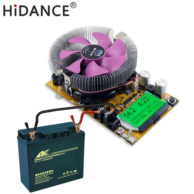
same seller, but this is quite a lot cheaper… don’t know what else is different except it has a more basic cpu heatsink without heatpipes.
by the way, this 2 models also have a good reputation on BG 8 In 1 150W / 180W Digitaler Batteriekapazitätstester Voltmeter Einstellbare Konstante C Sale - Banggood Deutschland sold out-arrival notice-arrival notice
EDIT: I was hoping it also had data output for logging, but I don’t think so… but a datalogger could be easily implemented with an arduino. If it’s a good product I would really like to buy it and mod it to get discharge curves.
interesting thread here ![]() Budget Discharge Tester Options for Hobbyists (Greater than 1 Amp) (and a little review in the OP)
Budget Discharge Tester Options for Hobbyists (Greater than 1 Amp) (and a little review in the OP)
What about the upcoming HyperJuice with 2x USB-C and 1x 100W output?
kickstarter.com/projects/hypershop/hyperjuice-worlds-most-powerful-usb-c-battery-pack

Zero Multi-Power Supply for Bread Board
A powerful power supplier board for your electronics project. Super wide output, 1.25V upto 24V
kickstarter.com/projects/349880250/zero-multi-power-supply-for-bread-board

Henrik,
Maybe you could review the Tronsmart U5TF Titan Plus. All ports support Quick Charge 3.0 and is rated for 90W.
I have it in queue, but I need some more equipment before I will review it.
I have ordered a couple QC triggers from China and they will probably arrive soon, it is this model: Test of QC2-QC3 trigger
With wires soldered directly to the circuit board they are good for my testing.
Thanks Henrik, looking forward to your reviews.
Ikea 3 port charger (new version)
Ikea LÖRBY
2.4A max per port
3.4A max combined
£10
Their charging estimate of 1 hour is wack. It’ll probably take about 2 hours to charge a 100Wh battery with a 100W charger.
Yeah. Unless you want to reduce cycle life drastically, a USB-C PD 3.0 port will never kick out a continuous 100W until the end. Unless they picked out an aggressive charging profile that charges at 100W power just until it reaches CV phase, which is not too healthy for the cells inside, even if they LG MJ1s.
Also, they’re using LG MJ1s, so that’s nice.
Hi,
Would it be posible to review this DIN rail USB power device?
MEAN WELL Din-Rail power supply 12W MeanWell (DR-15-5)
I’m plannig to use it on my next raspberry pi Project.
Thanks
We know the CV phase thing usually induces an additional top off delay largely dependent of the charging circuit output to battery path plus battery resistance. Since cells are spot welded that is usually quite low in a good powerbank, minimizing the CV phase time a lot.
By the way, the CV charging phase could be eliminated by monitoring cell voltage right at the battery terminals and cutting off charging right when battery terminal voltage reachs its maximum (usually 4.2V) and current tapers down to preset value. This is monitoring two conditions instead of one.
Cheers ^:)
The charge curve in all my battery reviews is done that way, it do not eliminate the CV phase.
Hello,
Could you please test Ugreen 2 x QC3.0 ports charger if you’d like?
Cheers!
Revisiting this a bit, maybe I messed up myself somewhat in the above explanation. What I was trying to say is that if we monitor cell voltage right at its terminals and use this value for cut-off, the whole I × R drop from the charging converter's output to the battery/cell terminals is eliminated. You say it does not eliminate CV phase, but at least for low internal resistance cells its duration must diminish greatly, doesn't it?
By adding a way for our charger to accurately measure current path resistance plus cell DC internal resistance, we could fill the cell or battery in one constant current go by adding dV = Icharge × Rpathplusbattery to the desired and cut-off monitored charging voltage wherever it is, with absolute cut-off (no tapering whatsoever). So, for cut-off voltage:
Vcutoff = Vbatterymax + (Icharge × Rpathplusbattery)
I am going to test that personally in my precision power supply and cutting off by hand, though I already know the result. :-)
Cheers ^:)
That depends on the charger, but yes many chargers reduce current early.
That would be outside the specified charge parameters.