Securitying / Mudder 2x XM-L lights (KD 2 Clones)

Aight, so being my pics in my “introduce yourself” thread got so much attention figured Id go through whole thing with my light.

Understand though I’m no expert, no fancy equipment just a good solid basic knowledge of things and love to tinker and fabricate things. But years in custom building rcs, being a ase tech, so on learned alot over the years.

First off Securitying and Mudder are the “brands” for this light on Amazon Prime. Being such, they get attention and alot of ppl buying them over Yinding. Though Yinding does 2 things better out of the box. I am ordering a yinding in a couple weeks with some other stuff, so Ill be applying my new “skills to it lol. And SS X3 (real not clone) be here hopefully tomorrow.

mudder clone

Version I have because I needed a light QUICKLY (commuter light broke)
Securitying Clone

Amazon clones are V1 of the KD 2. XM-L emitters not XM-L2 U2. Driver is the EXACT SAME (AWESOME!)

low/med/high all 3 can be programmed from 10-100% light output. Strobe is function of first turn light off the push and hold.

Problems out of box: well only 1, HEAT MANAGEMENT. The emitters are attached to a single oval shaped aluminum plate that is attached by screw from back side (remove rear cover/driver). This plate is 1mm+ from outer casing so only screw holes touch casing itself. Plus casing is very thin and light weight except back cover, it has meat to it,lol.

Output aint bad for something so small but thermal step down (yeap has that safety too) kicks in QUICKLY when light is on high. Driver (before losses) puts out 2270mA in series for emitters. Not bad.

Stock battery, seemed ok but I had SS 4x protected battery cases arrive day before I got this, so just yanked cells after initial test run, and used balance charger. Everything in box works, just cant say how well.

Onto the fun stuff, MODS:

Upon opening light I found the heat issue instantly, the aluminum plate for the emitters. How to fix….

Version 1.0 Aluminum plate 0.6mm thick (what I had on hand)

Simply cur plate, bent a long “tab” to extend internal length of top of case, drilled holes for mounting screws (had to elongate lower hole in emitter plate so could put a lower screw in) some thermal pastebetween plates, tab and case, plus front side of plate at screw holes, and away we go. Big help with heat but far from enough

V1.2 0.4mm COPPER plate.

Same thing but expanded to cover entire emitter plate and longer tabs to wrap around inside of case, more contact area since copper conducts heat twice as fast as aluminum. Thermal paste again of course. NOW WE’RE TALKING.

Can stop at v. 1.2 if keeping stock set up, thermal testing (get to that in a bit but figure 7mph wind speed) had it staying away from thermal shutdown down in safe range (high side but safe). Upgrading to XM-L2 U2 emitters, which I did on the STOCK PLATE using a soldering iron (mistake turned into way to reflow) helped temps a bit too because I could run “high” at lower level for same “visual” light output.

The “thermal management” testing equipment. All temp readings are in degrees F and taken internally at emitter backing plate:


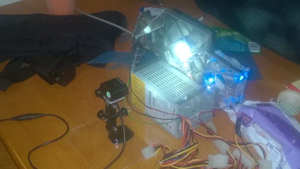
V 1.2 Thermal transfer plate and XM-L2 U2 at 100% test

“Air Flow Generator” is pretty obvious, things I had in a “junk” box in the basement. CPU PSU converted, 3 CPU fans then some lexan sheet I made into ducting.

All “cleaned up” and 12V DC power functional instead of fans just plugged into the wiring mess.

Light is mostly complete now, next post here will contain next “chapter” (wife and baby dragging me away from comp,lol)

Liking the test rig, i salute you sir :wink:

+1. Nice work and looking forward to the next instalment.

Chapter 2: XM-L2 U2 3C emitters, heat dissipation improvements, and increasing driver output.

Got a pair on 16mm and pair on 20mm noctigon mcpcbs. 20mm was too big (so emitters transferred to stock plate so i could see the differences in tint etc) to fit case as case measured exactly 20mm diameter but mcpcbs are actually slightly larger and no room on noctigons to file down enough.

The point was because I wanted to test a theory;

“Faster heat can be transferred from emitters to outer case, the lower the overall temps due to lower emitter temps” combined with this test I found HERE: Emitter Test Results Copper vs Aluminum . Shows higher output (and FLIR images courtesy of Ledoman) yet much lower emitter temps.

More on that later. Light is v 1.2 with XM-L2 U2 3C emitters. Next up was better heat dissipation by the case itself. So in comes Vancbiker (MTBR) with a cnc’d solution for these and Yindings:

And In first post shows standing temp on high (with air flow generator) of 150deg F. Next pic is v. 1.2 thermal test with the gopro/heatsink adapter:

21 deg decrease in internal temp!!! ~14% temp improvement Simply with that mount and thermal paste between it and case.

Next: Increasing Driver output. Another thnx to Ledoman for the “how to” for sense resistor mod.

Test of now pushing 2.77A (from 2.27A stock) to the emitters. Did try 3.29 on v 1.2 but thermal shut down was longer than stock but took around 4 mins with airflow generator. Case temps hit 170F. Mod was stack r500 resistor on top in parallel, 1= 2.77A, 2 = 3.29A.

2.77A output on high

8F increase in case temp but still below 140F at the hottest point (besides directly next to emitters) in case. NICE. Light out put on high was really sweet for something so small.

  • Side note: ALL thermal tests were constant controlled tests. Room temp, duration of test was 15mins with a 30 sec “cycle air off” to simulate brief stop for drink/catch breath during a ride. Vancs adapter did something that didnt happen prior. First tests before that adapter cycle off and back on of fans, case temp only dropped down 1-2 degs and stayed. With Vanc’s adapter case temps rose more slowly, a few degrees less (not max but total # of) and once fans back on, fairly quickly returned to “normal temps”.

Now things get AWESOME!!!

Time to use 16mm noctigons (with XM-L2 U2 #c already installed).

But how the heck do you pull this off…… For me a drill press with flat bottom ryobi 5/8” “wood” bit, drill, and a dremel with router adapter/high speed bits. First was the router adapter. Just a giant ring… so cut some clear acrylic 1/8” to fit bottom of router adapter. This way I have a smooth constant surface under the dremel and can control depth etc. And see the lines I draw on the aluminum as to where to “machine”. Drill press I got for free from Father, just one of the portable things you put a corded or cordless drill in but not in pic. Pic below is today (new project im starting on) but shows dremel setup etc for doing “hand made” CNC.

Next was deciding on aluminum stock thickness, went with 1/4. Making kind of a UNI-pill I guess would be the term. the oval backing plate but fits case properly all around and has “rings” on the front side to hold the emitters. After several hours, few cuss words etc later this was born:

Not as clean and “perfect” as a real cnc but not bad for very first attempt. Cut new, cleaner fit copper backing plate as well. Reason:

Noctigons have direct thermal path and copper, smallish holes in center of plate where each emitter sits, put copper in the holes (with thermal paste of course) then rear copper plate. Allows direct copper path to outer case. Not fully efficient copper path and aluminum plate has full contact with case including 1/4” worth of it on the sides, but copper is 2x better for heat than aluminum, so it helps vs leaving those holes just holes behind the emitters.

And current temps at emitter backing plate:

Another 9deg F shaved off best temp (stock driver output 2.27A v1.2 mods) but 17deg cooler than same driver set up (2.77A output)

So sweet lower temps, guess what that meant: DRIVER BACK UP TO 3.29A output per emitter… OH YA BABY thats some light. Temps no longer go to thermal shut down UNTIL I did 30 sec cycle off…. internal temps hit 165 (155 I think is thermal step down) but took time for thermal safety to heat up, my test is at copper plate attached to emitter plate. Fans on cooled down but not before Safety tripped. Quick reset and back to running temps returned to and held at 142F.

EDIT: OK just ran accross thermal step down threshhold, 158F (70C) but that means thermal safety ahas to reach that temp which is why took higher then time to step down.

Well you know light build up till now, Except some Carclo optics that came in yesturday. Current fit is one spot one rippled medium spot. Driver high program is at 90% which is a hair over 3A (like 3.02 calculated IIRC) and temps seem fine, yet to run thermal as I was playing with optics and luxmeter app for my windows phone (works but not sure how to properly test my light without some funky sphere). Driver, when I order from mouser aagain, will get resistor to set it at ~3.0A output unless heatsink add ons (coming soon to a light near you) bring temps down if I let it run at 100% instead of the current 90% program.

Little floody I think for helmet light, may go dual spot (have other optics from LEDDNA on the way too)

Current light pic:

NOW, next projects going: Gopro mounts for the taller hook shaped ones I found are 2 piece. Plastic base with clip then upper “hook” with tabs. On MTBR we are playing with ways to cool these down more. So the “hook” section of a gopro mount im machining, 1st the piece that fits into the plastic clip in base for gopro mounts the upper piece that will have the mounting tabs for the light and more heat sink fins (small and lightweight but some more lightly finned surface area). ANd we are talking with Vanc about a heatsink that we can use thermal adhesive or jb weld to attach to the tops of these and yindings. Again with small, sleek and light weight, but fins going front to back for proper cooling.

And Tonight I started ordering parts to do a plug in play remote switch for this (and for any other light I do like inbound ss x3 and Yinding when I get it).

first piece comes from last place I thought to check but stumbled on it. Push to talk remote adapters for walkie talkies and such… 2 wire, momentary switch perfect for these lights.

As for the “plug and play” design. Top secret atm as I gotta have parts in hand but rear plate has internal space between it and driver to put in a jack for DC style barrel connector, which I would put male end onto PTT adapter switch wires. Parts sourced, PTT adapter on the way (ordering a couple more later this week so I have spares and 1 for my oldest son), other parts ordering in the next couple days. Ill have around $12 in putting in remote on/off/mode selection that WILL NOT interfere with button on light head, simply work in parallel with it.

Only concerns are though caliper says I have clearance, making it fit and orientate it in a way that works and doesnt look all crazy, and mounting the jack down inside the backing plate. I dont fully trust “spec sheets” as they tend to round the dimensions a tad so gotta have in hand. Plus coming up with a “plug” to seal the port when not in use.

Now added aluminum heat sink base mount for gopro. Hopefully it draws decent heat.

Again amazing work. Your handiwork and abilities are to be applauded.

Ok so I found a Push-to-talk button adapter on ebay in the states. Ordered one as it looked like the one linked (i forget where think on MTBR yinding thread) and it is. So ordered 2 more lol.

Did the mod, extremely simple. tiny hole in back plate, ran the wire through, put an eclip on the wire to hold it from being pulled back out (wires for switch are TINY) since hopefully I will be converting this to removable switch.

AND IT WORKS PERFECTLY, love it. Now just to sew a piece of velcro to camelbak shoulder strap and gtg. THe included velcro would work but velcro on my pack will be a cleaner and easier to deal with look.

Great stuff….Really piss me off I can’t do those stuff!

Hey not a matter of can’t, its a matter of taking the time to learn. The tools aren’t expensive. Not for everyone cause it takes patience and bit of focus but beyond that google search and YouTube are your nest friend.

Hello there how things ?? Thanks for All the Help full info and tips on this link . Could you please tell me or point me in the right direction on how to mod a KD2 Driver to push the amps up to get a brighter light ?? I Am in the process of combining a KD2 with a Yinding and adding a Remote like you have , it will be interesting to see the two combined with a Modded Driver even maybe new Xml l2 if needed to maximise ever thing … Ps : there are like 50 Million ( not really ) xml l2 and tints could you recommend a decent one …

Thanks and as we say Down Under … Have A Good One …

Ilumin8

Hi and welcome fellow Victorian. I cant help you but don't forget it is Poets day today.

Hey there and Thanks for the Welocome , just checked out the website Brilliant idea and best of Luck with it . I have two little boys so no go there … Where are you based ? I Am in Sale …

Sorry for the late reply:

First off dont try to push the driver harder stock, youll burn the light up in a hurry. You saw all the mods I did, its so it doesnt fry the light.

Next is you need a R500 current sense resistor. Look on the driver near the black wire that goes to the emitter board, youll see a little resistor that has “R110” printed on it, you will need to VERY CAREFULLY solder the R500 on top of it. Thats the only way to increase output on these. Other mods like optics and good batteries help too. BUt without the mods your light will fry quickly.

Ive been doing tinkering with other lights too so Ill be posting threads on those at some point. Nothing as crazy as this or my solarstorm X3 (didnt have to machine special parts for the inside of the lights) But I have gotten some crazy output and great throw/spot light abilities out of yindings and others.

Hi there , sorry for the delay my side to … Work gets in the way of building things that shine … Thank You for the information I won’t push the driver on the kd2 with out better heat sinks ( it can’t handle what it has as is ) … I should have my yinding soon and then I will combine them and add a copper heat sink on the yinding but use the driver on the kd2 … I have just started reading up on a Cree XHP70 that pushes 4000 ish lumens … I have a 36 mm housing from Easy2led and am thinking of putting one in there , should be fun 12v 2.4 amp configuration any idea on drivers ?? … I Am in the process of fitting a 3 xml l2 star in the other 36 mm housing I have … To many projects to little time …

Regards

ilumin8

I'm a little way from you. Mount Evelyn in Melbourne. You have some nice mountain country out your way.

Number 5 Alive!

Nice light you built there. Really dig the above heat sink mods. Congrats :)

Someone caught the “Number 5” Thing,lol. Grew up on those movies. I noticed it after doing it, somewhere between number 5 and Wall-E