Ah, yes. :)
Man, there's so much content on this forum that subscribing on interesting topics doesn't do the job any more, it's hard to keep track on where I saw what... :/
Ah, yes. :)
Man, there's so much content on this forum that subscribing on interesting topics doesn't do the job any more, it's hard to keep track on where I saw what... :/
Yes, I have seen/heard about such. But then you are still stuck with the same UI. Would be nice to not always start on high, and would be nice to have direct off possibility. Yes, things can be done the Dr Jones way… But im no Dr… ![]()
I was thinking about either a high current switch (not sure which yet), or two lower current switches in parallel… It can be done… I don’t like the idea of killing the stock driver though, just for the sake of getting a contact board.
Does anybody know of a bare contact board that would be suitable to a SRK?
Just playing with the idea btw…
Old-Lumens has been using Radio Shack prototyping/breadboard PCBs cut into a circle, or maybe they're available in round, not sure.
You can also arrange components on the new board to leave room for long screws that extend thru the driver compartment and thread into the backside of the 'pill'/plate instead of relying on just the press fit into the body like with the stock piece.
does anyone have a working program available for download for the SRK?
i dont need super fancy perfect modes cause it takes forever for programmers to get all that they envision implemented while working full time jobs and family stuff.
id like to have something that starts out on low, has the same strobe function as stock, and has a med and high mode with no visible pwm that works on a atmel attiny13.
i know there are some one offs floating around.
i have the chips and the programmer. i just suck at programming.
this is not to detract from dr jones work… i know his will be top notch and id like to try it out in the future. id just like a simple UI with no pwm while we all wait for the best. ![]()
thanks
brian
stock SRK driver MCU can be used to drive 3x10⁵ boards (or 24x7135 group by 8x7135) with same electronic switch and minimum mod.
There can be a problem using AMC7135 chips in lights without a battery switch. If an LED is connected to the AMC7135’s and the chip is turned off via the Vdd pin, each chip can draw around 2 milliamps of quiescent current and the LED may light dimly.
I just ordered my SRK from http://www.cnqualitygoods.com/goods.php?id=1708
I hope to solder on the extra 30k resistors to boost the current. I bought the resistors for $1.50 including shipping from here: http://www.ebay.com/itm/100X-1-0603-SMD-Chip-Surface-Mount-Resistor-30K-30Kohm-Free-Shipping-303-/170902359963
I’ll also upgrade the size of the LED wires, add small wires from the sense resistors to the op-amp inputs for more balanced current going to each LED, and upgrade the ground path with large gauge wire ![]()
Will post before and after beamshots ![]()
-Jamie M.
You may not want to do that. Most of the drivers already have different value sense resistor combinations for each LED to compensate for the losses the in PCB traces. If you do it, you need to lift the pin on the opamp from the PCB and run the wire to the pin.
Ahhh, I did not know that ![]() Thank you. I will skip that mod and just proceed with the others
Thank you. I will skip that mod and just proceed with the others ![]()
-Jamie M.
Hi Serifus. Thanks again for your help! I used the rectangular pad directly to the left of the first terriod for ground. I then used the positive base leg of each terriod (I made a harness of 3 wires soldered into 1) to feed the aux power jack that I added. It worked but dimmed the emitters by about 1/3rd. Guess I should have taken your advice the first time. I tried the location that you circled and now all works as it should.

With 13 x 18650’s feeding the stock 6.5A driver, there is virtually no voltage sage and the light gets hot in a hurry. Its also noticeably brighter. Since this SRK lives on my bicycle, I guess I’ll just have to pedal faster to keep it cool! Im looking forward to tonights workout with the extended run time.
“Thin wires CAN carry a lot of current… if they are very short. Think of the bond wires inside a power MOSFET package. The SRK wires are several inches long. I didn’t measure the conductor size, but I would not be surprised if they were 30 gauge.”
The bond wires inside an LED also have almost no resistance because they are gold like most bond wires. I am positive you already knew that but thought others might want to know too. I am looking forward to using your final product (edit)if it becomes available for sale.
Yes, they do, but a bit thicker wires like AWG22 with silicone produces lower voltage drop.
It's like using a coated glass, or a bit better thermal compound... everything helps a little bit.
I own two Sky Ray king model flashlights. One of the lights has a single toroid and the tail cap can be removed. The second version is the original Fancy Fire 3 toroid version where the resistors can be stacked or replaced in the sensing circuit to make it brighter, I performed that mod but now that I want to remove the tail cap I noticed it too had been glued in place by the Chinese and I cannot remove it. The driver board was also glued in so I soldered a 12 gauge wire long enough to surround my hand twice to the center of the topside of the driver board. I put a stick in thru the switch hole to push and I yanked on the 12 gauge wire until the glue and driver board broke free.
Now I have one more problem. I cannot measure the tail cap current to see if any changes are noticed. The tail cap has also been glued in place and cannot be removed by ordinary means. I need some ideas of extraordinary means for removing my tail cap? any takers?
I just bought an SRK T6 NW from FF and interested to know how easy it is to replace stock t6 emitters with brighter u2 or u3 emitters. Anyone chime in on this?
Heat gun, strap wrenches, padded vice and a large can of patience. Were they trying to save the price of an O-ring or was the thing over torqued by the FNG at the factory?
Don’t remove batteries then try;
Using meter and jumpers, set tail cap down with batteries inside, a four battery parallel cradle could be used. Clip jumpers to barrel to barrel insuring continuity. Using edge wrapped (no short) copper washer of the right size with soldered wire, carefully center on top of + posts, thru meter, then down to driver board.
Being a FNG myself I would choose the cradle. Eye protection a must. Even with tail cap off, I had a difficult time getting reading without soldering tabs to back of battery for positive contact. Maybe someone who BTDT has a better procedure?

There you go!
I want to thank you all for this thread. I happened to get a FandyFire UV-S5 a few days ago. It has the three torroid driver, so I followed this post and changed the stock resistors out with the 6.8k ones. I didn't think I could do it, but with a big magnifier I was able to get it done. I threw in my set of 10 amp Panasonics and...
Shock, Awe, Stupid giant grin on my face like a little kid!
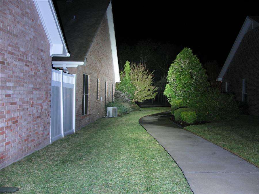

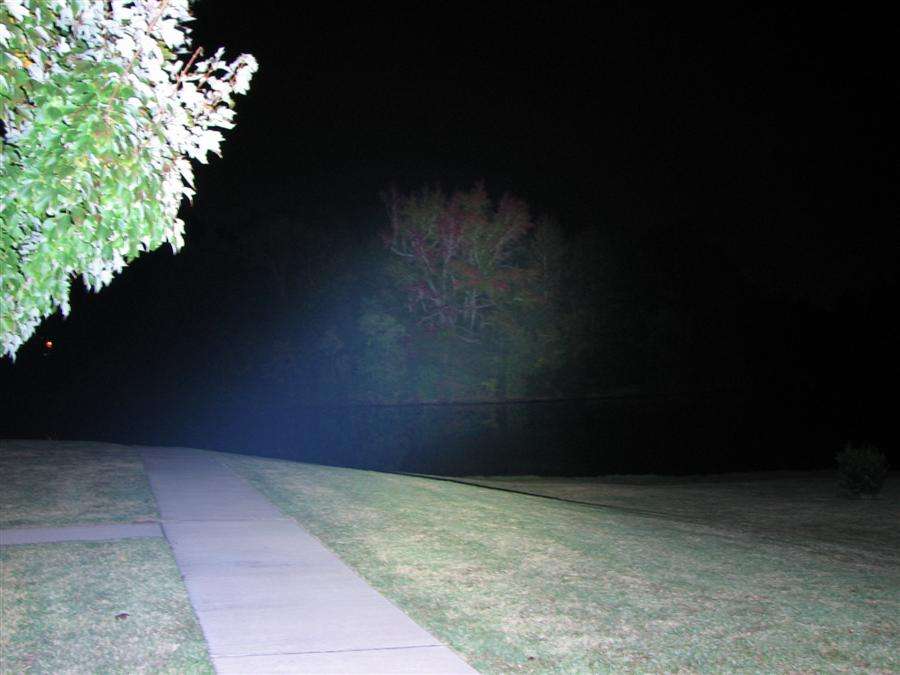
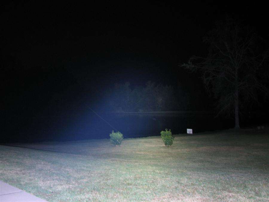
I think the haze is the light burning out the ozone layer, LOL. It's not blue tint at all, but the camera picked up all the haze in the air.
It has got to be the easiest mod I have ever done and about the brightest light I have ever held onto.
Thank you, Pavithra_uk
Congratulations on burning the Ozone layer. ![]() I bought an SRK too. I changed the sense circuit to 7.5k and replaced the LED wires with 18awg wires. It’s bright, real bright. I cannot hold the light(because of heat) after 2 minutes and pointing it at a white wall it is impossible to look at for more than a couple seconds. It’s an awesome light.
I bought an SRK too. I changed the sense circuit to 7.5k and replaced the LED wires with 18awg wires. It’s bright, real bright. I cannot hold the light(because of heat) after 2 minutes and pointing it at a white wall it is impossible to look at for more than a couple seconds. It’s an awesome light.
olympus620
Old-Lumens, that looks fantastic! You twisted my arm, so I just ordered some of those ultra tiny 6.8K resistors. :bigsmile: