Whether the star is DTP or not certainly has a large impact on the performance of the emitter, but I don’t think it would affect the measurements that I performed. At a given power, whether the thermal path is direct or not would affect the temperature of the emitter package, but the thermal power flowing down through the MCPCB and into the shelf would be the same in either case, so my measurements would be unaffected by whether the star is DTP or not.
For fun I estimated the thermal resistance of a non-DTP board (using equation 8 in the Cree pdf I linked above). I looked up the dielectric materials used and they are things like acrylic, epoxy, polyurethane… which have thermal conductivities in the range of 0.25 W/m*K. If the dielectric layer is 0.075mm thick and the thermal pad is 2mm x 3mm, the thermal resistance of the dielectric layer is 50 C/W, which is huge.
From my understanding a dtp would have a cooler led and higher overall head temperature. Rendering any data you have gathered here useless to anyone using dtp stars. I could be wrong but just my 2c
Like I said, I think the measurements I did are intrinsic to the hosts and describe thermal resistances of the flashlight heads. The thermal power flowing through the MCPCB would be the same whether it is DTP or not.
Your understanding is qualitatively correct. A DTP would result in better transfer from the LED to the MCPCB, and this keeps the LED cooler. Right after the light is turned on, this would indeed cause more heat to enter the flashlight head. But the LED package itself is such a small thermal mass that it would heat up and reach equilibrium quickly (probably in a couple seconds), and at this point the heat flow to the MCPCB would be equal for the DTP and non-DTP. For the non-DTP star, the LED would be hotter in order to flow the same heat through the less thermally conductive non-DTP mount. But the same thermal power will flow for a given LED power; this is a consequence of the conservation of energy. OK, this is not completely true; for large currents the non-DTP LED will become very hot and the efficiency will drop, meaning more thermal power will flow with the non-DTP MCPCP.
Very cool (hot?) measurements, thanks for doing this. It confirms my long-term observation that flashlights with well mounted DTP-boards can be left to become burning hot with no apparent damage to the led. It is really nice to see some data on this now
I’ve asked before, how is it we don’t have little heat-dissipating modules/heads/collars/fins at the driver/LED level.
There’s one nice illustration here, from Ronin:
Or take something like this heatsink,
with added threads into the center on the pin side to take the battery tube, and a bezel over the emitter on the other side of the heatsink
It’s not critical, yet — but we are heat-cycling our batteries rather dramatically with the hotrod flashlights.
That can’t be good, over the longer term.
40-60% efficience is false.
25-30% at manufacture specified currents, and much lower at currents that blf users like to drive.
Host and other external parts resistance calculations are wrong. You can use this method for selfcontained systems only.
I like this idea - making measurement in real hosts (I can add one more suggestion-make it with real cell). All this test on several kgs of copper or aluminium powered by 20amps current supply gives users lots of information, but this methods are good for science and not good for simple users. Conditions are far away from real life and most can make false conclutions.
I will try to make something but it is very expencive. Lux-rc fx-30 and fx-60 can disperse 8w and 16w (led power) and I can suppose that more half of their price is mechanical parts and machining. EDC triple or quad can take 30w from 1x18650 for 15-20 minutes. All wants more power, but nobody wants to carry heatsink that will make holding light turned on for 20 minutes able.
Yes, you are probably right about this. Lowering the assumed efficiency would mean there was actually more thermal power flowing through the host and would lower the thermal resistances values that I derived above.
I don’t know what you mean by this.
Technically, the idea of thermal resistance is only valid in steady state systems, which a flashlight heating up is not. But as I noted, the temperature differences between the shelf and the head were approximately constant as the host heated up, so I think these measurements can approximately be used to infer the shelf temperature (and junction temperature) if you know the temperature of the head and the thermal power flowing from the LED.
I’ll just add that while 150C may be the maximum junction temperature; according to Cree’s LM80 testing, you should keep the junction temperature below 100C if you don’t want the LED to wear out prematurely. Ideally, keep it below 85C for a long life-span. Above 100C, and you’ll never get the rated ~50,000 hours to 70% original brightness. You might get about 5,000 hours. Still a long time, though.
So, it looks like from your analysis, if you assume a 1.5C/W to 2.0C/W total thermal resistance, then a typical 1,000 lumen light which produces 5W of heat (and 5W of light), the junction point should only be about 7.5C - 10C warmer than the head of the light?
My guess would have been quite a bit more than that. Is the built-in thermal protection that some lights use, only for the purpose of not burning the user?
No. It produces 8w of heat, 3w of light. And 10-15C is difference inside led, difference between led die and led thermal pad.
Yes, built-in thermal protection protects your hands only. Big lightening systems work for years, but component are too hot to contact them.
Yes, approximately, unless I missed something in my analysis. Note that the XHP50 junction to solder point resistance is 1.2C/W, but the XPL thermal resistance is 2.2C/W
I guess so, and as you noted, to increase the life of the LED and other components in the light.
I don’t quite understand. Is this so the thermal power flow is well defined?
With a flashlight in air, only when the temperature profile has stabilized can you precisely measure the thermal resistance of the head. Before it is stabilized one cannot precisely define what the value of the heat flow through the head is, because energy is going into heating the head. When the temperature profile is stabilized you know that the heat flow through the head is equal to the thermal power produced by the LED.
Regardless of whether the measurement I did measured the true thermal resistance of the head (I think it is close, though), it can be used empirically to infer the temperature of the shelf if you know the head temperature.
The calculations depands on what do you want to count.
If you want to know temperature difference between two parts or two places of one part, you need to exclude heat transfert to air.
Heat transfert to air difference from lots of extra factors, it need to be calculated separately.
You can use heat transfer to air to set experimental conditions. For example, with a flashlight in air that has stabilized in temperature, the thermal power transferred to the air is equal to the thermal power produced by the LED. So then you know the heat flow through the head, and if you measure the temperature difference between the shelf and head, you can calculate the thermal resistance.
However, this is assuming that all the heat produced by the LED is transferred through the head. In my measurement, the shelf was exposed to air and so some heat was transferred directly to the air instead of flowing through the head. So you are correct that this would cause an error, but the surface area of the exposed shelf is quite small so the error would be small. (only the bottom of the shelf was exposed. The reflector and lens were in place during the measurements)
This was another thought, a while back, along the same lines (it’s hard to find heatsinks that don’t have nasty sharp edges)
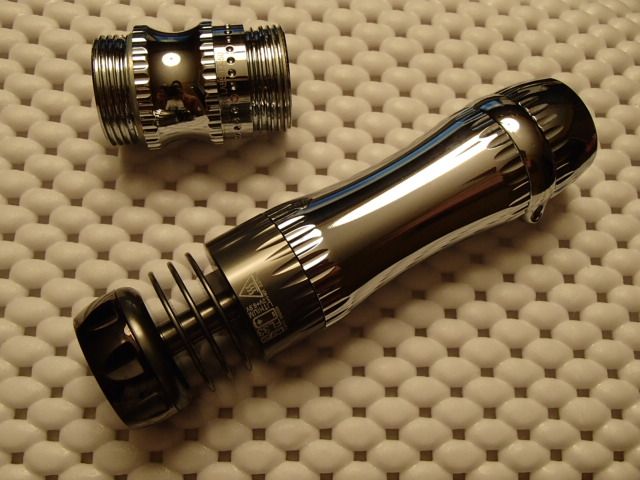
The earlier picture, the shiny metal thing with big fins and a little central hole, is part of a 3D printer.
Lots of heat-dissipation hardware out there, just not much for flashlights.
I will continue in this thread bacause it is more suitable as I think.
Here is Osram LUW CEUP.
It is made special for car headlight application.
It can be powered up to 1.5A (5W) according to the datasheet: LEDs, Lasers, Infrared Components, Detectors and VCSEL | OSRAM
Top bin provides up to 500 lumens from 1sq.mm die (XHP 70 - 4000/16=250 lumens per 1sq.mm )
There is no thermal pad.
All heat (5W*85%=4.25W) is transfering through two electrical pads that are 2*0.45*1.65=1.48sq.mm. (XHP70 thermal pad is 26.3sq.mm)
Heat flux is about 2.87W/sq.mm (about 1W/sq.mm for XHP70).
Rth is 5.7…7.3C/W (XHP70 Rth is 0.9C/W).
BMW, Opel, Mercedes, Audi are using Osram leds for car headights.
All they have at least 100000km warranty.
All they will have BIG problems if even one person will crush because of lightening problems.
Does anybody wants to say that their engineers are far away from “dream team” developers from company with head office in Shenzhen?
Perhaps nice to know, I did a test on the latest Oslon Black Flat a while ago, that undoubtedly has the same die as the LUW CEUP . The high surface brightness compared to any other led was indeed found in practice.
I’m not sure where the leap was made from a 105C max of a Cree emitter then the test emitter is a Lattice Bright. Lot of assuming going on.
An 12V emitter designed for car headlights compares how to the Cree emitter we use in our flashlight? What is the point of bringing in facts that are outside the parameters of the test?
This last question also applies to the external power supply used for testing. We use cells, they drain, rather rapidly in some applications, so the constant heat source does not exist for us in the real world use scenario and all that testing is dirty water down the drain.
Perhaps thermal probes placed at strategic locations would help test an actual light under simulated conditions, which would still be inaccurate because we use a light under a wide variety of ambient relationship… downright cold to 110 degree F ambient, humid to dry, even wet in rain. Gloves not taking heat from the light as compared to bare hands acting as some form of external sink. Our real world use situation changes nearly constantly, rendering the tests invalid.
In the end, we have the worlds top scientists feverishly working to predict the next move of a woman… we all know what happens next in THAT scenario.