Just took a quick shot of my K40vn. Here -
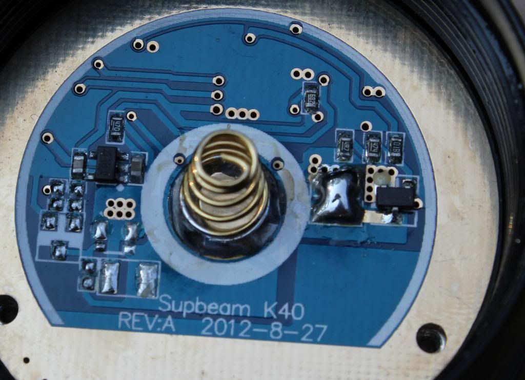
One more img of the driver from K40 I just received today ![]()
(click to see it in 100%)

Edit: haha, so now you have modded and unmodded to compare :bigsmile:
Just wanted to add that jumping the resistors on my K40 L2 read 3.35A tailcap current at 11V input.
Here’s a quick video demonstrating the voltage vs current consumption:
So, with R100 (0,1 ohm) and R082 (0,082 ohms) in parallel I have total resistance of 0,04505 ohms,
and if I would to be more conservative with resistor modd I need to find something like R020! right?…
Thanx rdrfronty & Sirius9 for your pics. Its clearer to me now. The resistor missing in my K40 driver is spec’d 682.
When I did ryansoh’s mod style, my battery carrier reading is 2.06 A (6.18A effective?) and now that I did a direct wire, its 3.77A (11.31A effective?). When I removed all additional resistors going back to stock, my battery carrier reads 1.35A (4.05A effective?).
I don’t think I’m having a problem with battery carrier readings as they seem normal. Its the current going to the LED that remains a mystery to me. It could be my DMM but my lux readings also seem to be consistent with my LED DMM values.
Does anyone know stock vs modded efficiency on these?
It seems to be around 75% (after mod)? I cant remember to have seen good numbers on input vs output..
I copied what others did in getting the current readings. I made lead wires for my DMM using AWG 16 automotive wires, alligator clips and banana plugs.
After completing my new lead wires, I tested getting the tail cap readings of my flashlights and found out that my previous readings were much lower. My previous test leads (the ones that came with the DMM) ain’t good enough in getting the exact current readings.
I tested the LED current reading of my K40 again but after removing the direct wire and adding 4x R100 sens resistors in parallel with the stock resistors and the results were just astonishing. I’m getting 5.06 Amps to the LED using my new lead wires while I can only get the max of 3.04 Amps to the LED using the lead wires that came with the DMM.
I guess my K40 is not that bad after all. :bigsmile:
I removed all sens resistors and copied the direct drive done by vinh as posted by rdrfronty - replacing the resistors with a solder blob. I also shortened the lead wires (AWG 22 from IOS), cleaned all brass parts with alcohol, buffed the back of the copper star as well as the pill with 1000 grit sandpaper, placed thermal paste (I’m using Fujik thermal paste sold by DX), then reassembled my K40 but leaving the negative lead wire unsoldered for the LED readings. ![]()
Now using my new test wires assembled yesterday, I took the current readings at the LED using my cheap DMM and here are the results:
1. Level 1 - 0.00 Amps
2. Level 2 - 0.50 Amps
3. Level 3 - 1.35 Amps
4. Level 4 - 3.61 Amps
5. Level 5 - 5.47 Amps
6. Level 6 - 6.25 Amps ![]()
Vinhs 6.5 Amps is real after all and there’s absolutely nothing wrong with my K40. Its the sloppy test wires that came with my DMM that been giving me crap readings. ![]()
That’s great to hear, thanks for reporting back.
It’s very interesting how DMM leads can make such a huge difference.
Yeah! I refused to believe it at first until I found no other option in ‘troubleshooting’ my K40 driver. I’m glad I made a new set of DMM test leads. :bigsmile:
A resistor marked “682” would be 6800 ohms (682 means 6, 8, two zeros).
Oh I see! ![]() Thank you very much texaspyro! :bigsmile:
Thank you very much texaspyro! :bigsmile:
I think I’m using a resistor with 587 760 330 markings in it. But anyway, I’m still getting the LED Amps that I wanted so I think that resistor has no significant effect. ![]()
So may I know is it okay to jumper the resistors to gain high current draw while not drawing too much (i.e. >7A)?
I jumpered them out, like what vinh does. He's done dozens of them that way and sells them like that. The driver is identical to the TN31, so, you should get 6 to 6.5A to the LED, while measured at the carrier it's much higher. There are large loss's through the carrier, through the driver and wiring.
Yup, you can bridge them together with solder because the driver is voltage limited to about 4.5V, and most XM-L2’s won’t go over 6-7A at that Vf. Using a good thermal compound is a must and lapping both surfaces are recommended for best heat transfer. ![]()
Thanks for the prompt reply Tom and ryansoh. This K40 is so tempting that I wish to order one from Vinh but despite of his undoubted good work it’s quite expensive at the same time especially after adding the shipping cost. I am thinking of buying one and mod it by my own.
So do you guys mean that the crazy high ampere of 9~11A was measured at the battery carrier while the LED current was actually around 6~6.5A?
I think what Tom meant on post #19 was that he read 3.1A from the battery side, and if the driver were 100% efficient, yes that would mean that the LED was getting about 9A, but the driver’s efficiency drops drastically as we push it to its limit. So only about 6.5A is going to the LED after the energy loss in the driver. ![]()
The K40 is one of the easiest lights to mod, despite its relatively high price, so I don’t think you’ll have any difficulty creating your own thrower.
Thanks ryansoh to clear things up, now I roughly have an idea of how to mod this little beast.
For the current, just jumper the two sense resistors.
For the emitter, I will buy the XM-L2 U2 version so just dedome it will do. Of course apply AS5 underneath.
As for the focusing/LED positioning, did you guys do anything special to re-position the height of the LED? From Vinh’s description of his K40vn he says he would adjust to the optimum focus, does that mean the LED need to be raised into the reflector?
And Tom E did use the strap wrench to disassemble the head, magnetic ring and so on as shown in the OP and they looks pretty tight. if I just want to tweak the light for maximum performance do I need to disassemble all these things? I think no?
For the sense resistor tweak, you can solder out the two resistors and bridge the two pads with solder.
Dedoming with gasoline increases the throw dramatically and with the current boost, it becomes one of the best performing lights for the money.
The tint does become warmer with a slight green hue.
Although not specifically tested, I think lapping the copper PCB would be a good idea too on 800 to 1500/2000 grit sandpaper.
As for focusing, there are some patterns around the hotspot, and depending on how you screw the bezel in, it shifts around. It’s hard to explain, but I think you’ll know what I mean when you play around with the K40. I didn’t use anything else to change the reflector’s height, and the centering ring does its job without a hitch.
My version had an unglued head so the lens, reflector, LED, and PCB were accessable. However, there is a lower thread just above the magnetic ring is glued for mine and Tom E successfully dismantled it with two strap wrenches and a heat gun. I couldn’t do it with my hands with gloves. You don’t need to do that for performance improvements; however, you can clean and reapply some lube for the control ring if you’re not satisfied with it.