I’d rather not have.
TomE, be a sport and take one for the team, see if the driver can do 10A :)
led4power, what would be required to make this driver reliable at 9-10A? How much would that increase the cost?
I'm sort of confused at this point... Triple parallel LED's should be no different whatsoever to a driver. You are just running each LED at a lower current (non-turbo), so for high mode, take 5A / 3, and you have current per LED. The LED's operate more efficiently with a lower Vf - everything is fine. If in turbo mode (effective DD), you will be able to achieve higher total current because of the lower Vf -- this is where it can get dangerous in theory... If my max amps is ~5.4A now to a single XM-L2, it could be much higher to a triple XP-G2, or triple XP-L.
Also in theory, driving a sinlge LED with 3-4 cells in parallel, in theory you should be able to get a little more amps to the LED than you can from one single cell. Again, the driver doesn't know or care.
For the driver heat sinking issue -- I'm also confused now. It's the components that will get hot -- which components? You mentioned the MOSFET, so that should be the focus... Adding contact surface to the ground ring may help some (standard pill mount method), but it's probably not very effective. You really need to heat sink the specific components, and maybe the solution in post #53 would work well for that. I guess we need to come up with some sort of guideline or criteria of at what amp level we need to heat sink at.
Heat is problem,nothing else,so if you want 10Amps,just like in other electronic applications mosfet should be mounted on "heatsink".In flashlight world that probably means mount it on the bottom of pill(but it must be electrically insulated for body).
Tom, what kind of stack height do you have clearance for in that light? I’m thinking that if you cut the appropriate length of 3/4” copper pipe, slice it lengthwise and take out the proper sized strip so you can close it and make it fit around or onto the LD1 ground ring, you can solder this piggybacked driver to this section of copper pipe for a heat sink. Should be very effective, and you can add copper onto the components that need sinking, solder it to the pipe ring then use thermal paste to join this web of copper to the component.
Soft copper is fairly easy to cut, should be simple to do and give a lot of thermal path to that driver. Hard copper like water pipe would be a greater challenge.
Edit: by stack height I’m asking how much clearance you have above that driver inside the pill. 1/2”? 3/4”? A ring of copper pipe falling just short of filling the available space could give a lot of heat sinking to the driver.
Edit II: if there’s space side to side, a second ring spread a little wider could be snugged over the first one, the 2 could be re-flowed together, and effectively double that heat sink mass.
Triple led has lower Vf so if current is the same,driver must burn more watts (Ubatt-Uled)*I. Triple xp-g2 at 10Amps probably has high enough Vf so that driver would be "out of regulation",and in that case generated heat would be low (I^2*Rparasitic).
But with triple xm-l2/xp-l Vf would be very low,maybe 3.3V,and dissipation would be quite high, cca 5-8Watts-too high for mosfet with bad thermal connection(that amount of heat is equivalent to xm-l that runs at ~3Amp!)
Of course if you pick battery with higher internal resistance,dissipation drops,as I said it all depends on this most important equation for linear drivers: Pd=(Ubatt-Uled)*I.
The manufacturers typically play it very safe, not being able to control which cell the end user sticks in the light. Uncontrollable variables.
Dale - not sure of internal clearances. If I got time, maybe can check this evening (@work) - I know it's not super tight but not spacious either. I'm behind @work - will need to spend some long days @work for a while and I'm cutoff from my 'flashlight factory' in the later evenings for the next 1 1/2 weeks because of family staying over, then vacation... Oh boy, not much time for fun  .
.
I’ll play with it some…
J)
I got one Y3 (1 cell) with the LD-1 driver, one stock Y3 (1 cell), and one Y3 (2 cell) supposedly RIC shipped yesterday, on the way.
They’re all gonna rebel on you, leaving them idle and not playing with them. Especially that one with the LD1 driver. It needs companionship and outings…just sayin.
Would it help to apply a small copper heatsink like this to the mosfet?
I've done a few calculations and I don't think that the driver will ever really have to dissipate much more than 5W.
I've chosen modes of 0.2A, 1A, 3A, 7A and 10A (because they correlate easily with HKJ's graphs).
I have chosen the Efest IMR18650 2500mAh as my battery. Source: https://budgetlightforum.com/t/-/26281
%202014/Efest%20IMR18650%202500mAh%20(Purple)%202014-CapacityTime.png)
And I'm using a triple XML2 for the LED voltages. Source: https://budgetlightforum.com/t/-/16621
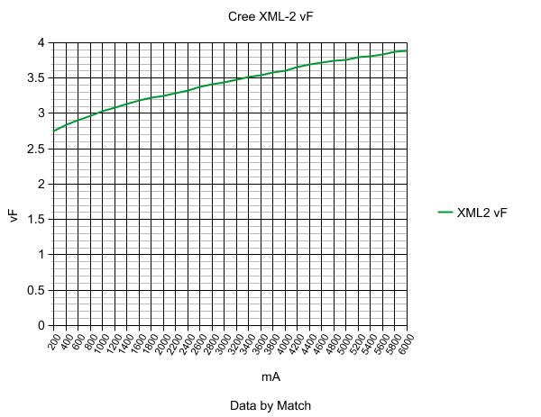
Note that in each mode each XML2 will only see 1/3 of the amps.
At 0.2A: The battery should easily maintain 4.15v, and each XML2 will have a Vf of 2.75v. The driver will have to dissipate (4.15v - 2.75v) x 0.2A = 0.28W
At 1A: The battery will start at 4.15v but go down to 4.1v within 5mins, and each XML2 will have a Vf of 2.8v. The driver will have to dissipate 1.35W at the start, and 1.3W after 5mins
At 3A: The battery will start at 4.1v but go down to 3.95v within 5mins, and each XML2 will have a Vf of 3.05v. The driver will have to dissipate 3.15W at the start, and 2.7W after 5mins
At 7A: The battery will start at 4.0v but go down to 3.7v within 5mins, and each XML2 will have a Vf of 3.3v. The driver will have to dissipate 4.9W at the start, and 2.8W after 5mins
At 10A: The battery will start at 3.9v but go down to 3.55v within 5mins, and each XML2 will have a Vf of 3.5v. The driver will have to dissipate 4W at the start, and 0.5W after 5mins
These values are with a unprotected IMR battery (which I assume most people will use to try and squeeze out maximum amps). Using a normal battery would result in lower power dissipation in the driver. However, using a 4.35v battery will increase power dissipation in the driver a lot.
It also seems like 7A might be at the point where the driver is feeding lots of amps, but the XML2 still have a relative low Vf. If we used modes of 0.2A, 1A, 3A and 10A, we would limit the power dissipation to 4W and less. Would the driver be able to withstand this with proper heatsinking? And also, would the over-temp protection not help the situation, since limiting the driver to 3A or less would bring the power dissipation down to 3W and less.
> Soft copper is fairly easy … Hard copper …
heat annealing fixes that