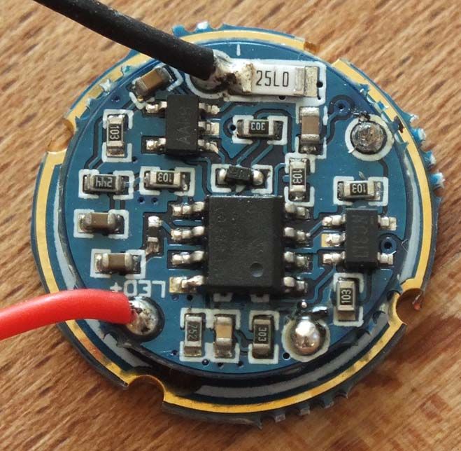
There is a similar discussion in a different thread, somehow this driver never developed an “official thread” yet…
relic38 mentioned the resistor near the negative lead to be the sense resistor. So this should be the “25LO”, mine came without the yellow goo of your’s. 25LO seems to be 0.025 Ohm and somewhere I read that sense resistors tend to be very small.
relic38 also said you would increase that resistor value to get a lower current. My guess is this whole thing works linear, as Kokopelli wrote here
The following is my presumtion (the math is correct, but the conclusion might not…) so please take this with a grain of salt:
Lowering the current needs higher resistor, thus changing the existing one completely.
Increasing the current needs a smaller resistor, adding one in parallel will do that. So:
0.025 Ohm = 3 A
add 0.330 Ohm in parallel (=0.02324 Ohm) -> 3.22 A
add 0.200 Ohm in parallel (=0.02222 Ohm) -> 3.38 A
add 0.150 Ohm in parallel (=0.02143 Ohm) -> 3.50 A
add 0.100 Ohm in parallel (=0.02000 Ohm) -> 3.75 A
and so on…
I’d like to verify this, but I don’t have any SMD resistors at all, let alone these small values, so I will need to order them.
Furthermore I’m a bit hesitant to increase the current significantly, because PilotPTK wrote (for a different driver)
Luckily HKJ promised to include this driver into his large driver test.
Thanks for that info. I was looking for “Rxxx” for the resistor, so now you’re clarified that.
I don’t have any SMD resistors either, but I do have some low value power resistors, so I can try a 0.35 ohm one to see what it does, and then go from there.
From my testing, this driver outputs about 3 amps by default, and I’m trying to find a driver for a DST, so was thinking of this, but want a little more current, and thus my question(s).
I was able to remove the flux off of the chip, and here’s a new pic:
As you can see, this confirms that the chip is a “25LO”.
It looks like the negative (black) wire is soldered to one end of that chip, so I did a test where I shorted from the negative wire to the other end of the 25LO chip, and it didn’t affect the emitter current (it stayed about the same).
I sometimes use my old crusty tweezers to short across (suspected) sense resistors while measuring output current. They're not as low resistance as a piece of solid wire but are still low enough that it'll show an increase in output.
I was running a short lead from the end of the black wire to the other end of the resistor, so that might’ve had some resistance. I’ll try the tweezers as you suggested.
Ok, I tried the tweezers to short the resistor, and saw emitter current going to about 3.46 amps, so I figured that I’d go ahead and short the resistor, just to see what happens.
I soldered a short piece of wire across the top of the resistor:
Then, I tested, and got:
Yep. 4.43 amps. And the scary thing is that the current keeps increasing, slowly, even on some TF 18650s.
The driver still has a somewhat high medium mode:
But, the driver appears to no longer have a 3rd mode anymore (i.e., no “low” mode).
I’m not sure if I’d recommend this (shorting the resistor), but it’s ok for me. I can go to the “medium” mode, and then, for brief periods, go to high mode.
I also noted that if left on high mode, the driver would shut down, so that’s a good thing to prevent killing the emitter.
Well, I put it into a DST, and it’s working with 3xC and 1x26650 (in a clone short body), but I don’t have any body/tube that’ll work with 2x18650 or 2x26650 with the DST, so no way to test “the full power”…
Also, BTW, I was able to get 2 Li-ion batteries, using the same config as my earlier short DST, 2x18350s. After I did that, I realized a problem: I can’t tell the difference between the “medium” and “high” mode now… they are just too close in brightness. It’s a problem because my “plan” was to use it mostly in medium, with occasional short stints as high, but, if I can’t tell the difference, I end up leaving it in high mode unintentionally. So, I think that shorting the resistor is kind of impractical…
That's why the multiple very low ohm resistors are useful, each one added might give you something like another .1-.2A. Also, something that happens with those 'V10+' drivers, the medium mode is set at a level as if the high mode actually would deliver the rated 5 amps, but it doesn't, so they appear to be about the same output. You could be seeing the same thing if the smaller cells can't put out enough to fully run the high mode, it makes them appear too closely spaced.
As I said earlier, I don’t have any of the SMD low ohm resistors. I’ll probably try to remove the shorting jumper later, if I can. I’m especially curious if the 3rd mode will return :).
FYI, the 18350s are the same pair I had in my MT-G2 DST, and I was able to get 4.81 amps with them in series last night in the MT-G2 DST.
For the record, I really can’t recommend shorting that resistor. I was doing more testing last night, and it kept shutting off, so eventualy went to bed. Then, when I tried it this morning, it would come on, but only dimly, like a moonlight mode.
I tried to remove the short across the resistor, but then the driver was dead… Actually it was weird, it worked once, but not after that.
So, I’ve replaced the driver with one I pulled from a half-worked light, and my DST is now good again, pulling about 3 amps at the tailcap and has modes (so the emitter was fine).
It’s possible that a low resistor would’ve worked, but I don’t have any, so I didn’t have the chance to try it.
On another thread, it was already mentioned that Hank Wang had been asked this question, and he said that it (driving an MT-G2 with the LD-2C driver) wouldn’t work.