Could do that - good idea, but again, TA doesn't want it working this way, so didn't bother any further.
Thanks a lot ![]()
I can state success for the Narsil build with the E-switch plus forward switch
Tom E changed the code so that the light gets always in turbo mode when the battery is conected here
This is the same as it was in the Klarus XT11GT light.
the normal narsil is running on my mopdded Skilhunt H03R
also adjusted the thermal calibration, works perfectly
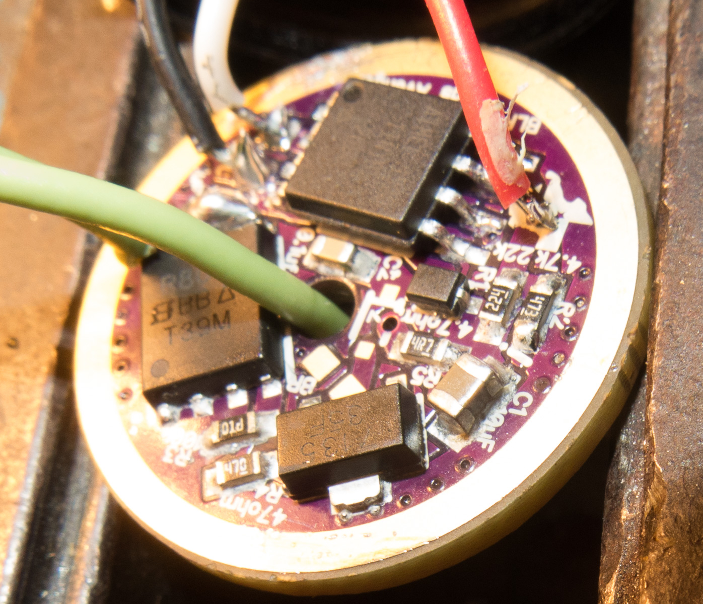
black and white goes to swich with indicator LED which is feed by pin 7 over a 4.7kOhms resistor

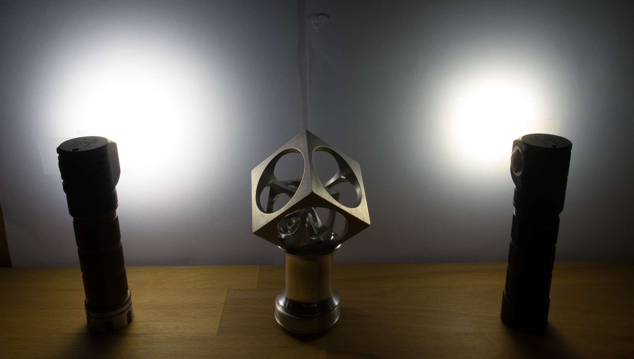
left with TA 21mm driver, on the right stock with TIR both with identical high drain cell
left 4.55A right 2.45A
Glad that worked out. I'll be adding that into the mainline code for both Narsil versions. Right now I got another driver project to work on - might be tied up with it for a week or two.
So actually it turns out lexel's request should "just work" in bistro-hd, just not a case I'd taken the time to think about enough. Enabling e-switch without any other timing control should just do it. Using memory or a high output first mode is probably desireable for that. I suspect it works even with the bugs of the present release since I can't think of any that impact that setup and it's actually one of the build configurations that I actually did some testing with, but the next release is hopefully a little more stable (closer to beta than alpha anyway).
It's official, OTSM is working on the original version board. No more worrying about cap temperature, or OTC calibration, or sensitivity to changes in resistance, click timing is defined as actual time ex: short click < 0.5 s med click < 1.5s, long click > 1.5s, and it just works.
The build component details are here:
https://budgetlightforum.com/t/-/44344/69
Software is in the OP of that thread.
The firmware build is pretty heavily tested now (if I didn't break something with that last little change, there's always that one last change ;) ), for both standard TA-OTC and TA-OTSM. I'm using OTSM in a light and it's great. Voltage calibration is dialed in perfectly for both (the first using the divider, the second using Vcc) for me, but of course could vary a little from light to light. For the divider builds calibration is super simple. Vcc calibration (for OTSM) is slightly more of an art maybe, but seems never terribly wrong anyway. It's harder because Vcc has two unknowns, the internal reference calibration and the diode voltage drop, but I hope we'll find that just tweaking the offset number gets everyone close enough anyway.
As a bonus there's tons of room to spare in the firmware for TA to finish off those missing modes. (Actually there's even room for those low Vf regulation curves we talked about).
Excellent! I haven't been able to keep up, but now that you have it pretty solid, I gotta check it out.
The 25 and 45 V versions I might not have - gotta check stock.
Great Job on this! Persistence paid off!
heck of a saga to replace one stupid cap, lol.
Excellent!
Can it match the existing TA PCBs?
Oh and you don't abosuletly need to have the V version. Just fuse it as if it's a V (which is what is standard anyway it seems) and it's working well enough now that I think it will be ok. All my original testing was done that way. Aside from probably getting a bit worse off-times, the issue is corruption, but worst case, you reflash it eventually. I think the main corruption risk is eeprom, but I'm not sure there are eeprom conditions that bistro won't recover from, at least with a menu reset. It may not be so bad.
If you mean can you build it on them, yes, mine is a 17mm version. The C2 cap is a slight squeeze, but not a big deal.
Would you post a photo?
Thank you.
Nothing to see. It's just a TA build. The C2 cap is just and 0805. Don't take me litterally, nothing is actually squeezed. I think TA's pad size standards are larger than some spec systems anyway, or anyway, large enough. It's not an issue. It's actually already written in his instructions that it takes 0805's, and it does. Anyway, the driver is closed up in my light now. Finally off the test bench!
This is great news! I have not had time to mess with anything light related past a few prototypes I promised to test out recently so I have not messed with it personally but look forward to doing just that.
I have the Texas Commander driver done, I just need to find time to put together all the files, upload it and then put together the parts list and description thread.
I have been thinking more and more about the future of drivers for BLF style lights. We are running into an issue where the Vf is getting low enough that direct drive is no longer practical but buck drivers are too weak to do what we want.
Buck is the best option and for lights with big enough driver pockets they are what will power the future for sure but for lights like the S2+, this is not the case.
What we need is a 7135 style linear regulator, and/or an FET with a thermal pad. The Texas commander works fantastic, the only issue is it simply can’t dissipate the heat due to not being able to have any heat path to the body of the light. The 7135 has a thermal pad which allows them to handle more power.
anyone know of such a part?
The options are very limited if no better options are to be found for linear regulation with a thermal pad / path. With a thermal path I think the Texas Commander could handle 3W+ of heat which would be enough for most single LED’s to regulate the entire current range.
I have also recently become aware of the 841 MCU, this (or another similar / better version) is the true future of flashlight drivers IMO. More pins, more features, newer, lower drain, and most importantly a fraction of the size of what we are using now.
With firmware quickly moving to an era of no longer needing separate firmware for clicky and e-siwtch this would not be possible as we should not have to reflash the driver much if at all.
What did the final compiled size of the firmware come out to BTW?
... and actually I think there is an 0604 version of that cap, but it's 6.3V instead of 10 if I'm not mixing things up. That should be ok for a 1S light. Just keep in mind that Ta caps tend to go BANG if you push them too hard.
Well TA, one option is we get that regulation curve into the remain gobs of space I made in bistro-HD. It's not as elegant though, more of a bandaid.
Yes, this is the most likely option at this point unless a new part can be found. Sad, I am sick of 7135’s.
I have a few ideas that might work ok but not as ideal as I would like.
The best idea I have come up with is actually fairly simple. Just get some custom mcpcb’s made with a pad for the FET on the mcpcb itself. Thus allowing for virtually unlimited heat dissipation with good regulation via an opamp driver. As a side benefit it would free up a lot of PCB space on the driver for more components and more edge clearance.
This is the most practical option really except for having to get those mcpcb’s made. I need to see if the FET would even fit on a 16mm star with the LED, I am not sure that it will and it might cause issues with the reflector as well. With a 20mm star it should be ok but that would not fit a lot of lights.
Although maybe a smaller FET could be used with such a good heat path, a little extra resistance would not be a bad thing with these super low Vf LED’s.
The normal SIR800 FET will just fit on a 16mm star but it will also interfere with the reflector and centering ring, needing mods to the reflector and a custom ring.
I wounder if a smaller lfpak33 FET would handle 5-10W of heat dissipation on the mcpcb?
What about two of them?