Texas Avenger "TA" Driver series - Triple channel + Bistro or Narsil + Clicky or E-switch - The Ultimate open source driver!

In fact if I were going to try do it (well...) I might just buy one of these:

https://www.amazon.com/DROK-Continuously-Adjustable-Step-Down-Transformer/dp/B00C375W3I/ref=sr_1_3?s=electronics&ie=UTF8&qid=1473999419&sr=1-3&keywords=constant+current+10A+buck

see if it works, maybe figure how to beef it up slightly, maybe not if really handles 10A, and just try to copy it but in a 46mm diameter layout, but it's a lot of stuff crammed in. The pots can go at least. Even that plan doesn't look easy.

The parts are apparently easy, the hard part is the actual layout. At high currents there is a lot of EM fields being created and they tend to play havoc on everything in the circuit.

More than a few have tried and failed I am told.

How about the MTN-MAX drivers? Richard has shared the board on OSH Park. Maybe he would be okay with stretching the board out to the SRK size and adding your quadrant layout on the bottom. Incremental changes don’t always happen in one person’s design, they sometimes pass from person to person. Most of the BLF drivers were made by somebody looking at somebody else’s driver design and wanting it just slightly different for various reasons.

I talked to him about that and he said I was welcome to try it but also said he does not recommend it.

He said he straight up got lucky with the layout on that board and has had trouble making another one that worked. I decided to take his advice and leave it alone till I had the time to start from scratch.

He gave me a much better buck converter IC to work with that should be much more reliable but would also need to start from scratch on.

I still want to try it at some point but that will be something after the TA drivers are completely finished and when I have a lot more time to play with it.

I want to make some Avenger drivers with LDO option along with the 4S SRK driver and a Q8 driver with an extra bank of 7135’s (possibly the same as the 4s driver but not sure how feasible that will be). Also if any changes are determained to be in order with the ability to remove R1/R2 then I would make a few new drivers with those removed and pads for other options.

Minor things but still things I want to finish before moving onto other drivers.

I'm work'n on a 15 mm 85 based driver now, to update the firmware on. It's a wight driver using the small footprint FET, but didn't need any extra parts like a C2 or FET resisotrs for it work stable. Of course it was never scoped, so really dunno if I'm just lucky or not. It's in this light, the SolarStorm SC02: https://www.fasttech.com/products/1601/10005040/1669500, actually pretty good deal at that price. Has a real SS bezel.

Well, if you copied his driver layout, wouldn’t it work just like his driver? I don’t understand how it could be different. As for the better buck converter IC, is it possible that they have a ‘typical usage’ schematic with the datasheet and some recommendations for component selection and placement? Surely the manufacturer wouldn’t leave the user to figure out how to use their chip. Maybe DEL could find some time to help with component layout for a buck driver as well. Have you asked?

Apparently RMM tried resizing it but it didn’t go to plan, that why he pulled the 20mm version. I am just going on what he said.

The new Buck IC is from TI so a much better part, it does have a schematic for layout but the datasheet is really really long and I have not had time to really dive into it.

This is the IC that Richard recommends: http://www.ti.com/lit/ds/symlink/lm3409-q1.pdf

I actually ordered one IIRC with my last digikey order.

I had actually started a thread about such a buck driver awhile back but no one really seemed interested in helping with the design at the time. I can read a schematic alright and even adjust minor things but the big picture of how it all works together is something I prefer to leave to those that truly understand it.

I still want to do a buck driver at some point though.

TA - if you are interested in doing a small 15 mm driver, let me know. Here's what I had in mind for my ideal 15mm driver:

  • make it FET+1 - probably can't afford space for a triple, even vertical space is usually very tight when I use these, in 14500/16340, and several small e-switch 18650 lights as well. Will probably use the thin board OSHPark option
  • small LFPAK33 FET is fine - Richard and wight, others have recommendations - I got them as well
  • eliminate the R1/R2 resistors - I'll work on the 1.1V ref version, as per DEL
  • do the DEL design, partially at least - the 4.7 ohm is important to precede all circuitry, accept the LED+ of course
  • need pads for pin#2 (OTC or switch), and also an external pad for pin #3 (just one - I can get grnd from lots of places)
  • if can't fit full 85 layout, it's fine to go with bent pin method, just ensure clearance for programming clip
  • according to DEL, should be ok to drop the C2 cap as long as we got the 4.7 ohm resistor in
  • for the FET resistors - dunno if necessary. Probably need info from DEL. Might not be so necessary with the LFPAK33 FET, maybe? I would definitely use/try these without the FET resistors

The big difference from what we have on OSHPark and/or from Richard is the 4.7 ohm resistor, full pads for pin #2 and #3, plus the savings of space with eliminating R1 and R2. Whatever you can do to keep space on the grnd ring, or make it as wide as possible, or leave one edge of the board with free space, that would be great. Sometimes I have to file down one or 2 edges of the driver to fit it into a tilted position.

Like this:

Well if you want it just for stacking Tom, TA can get rid of the space-wasting spring pad.

If I can fit a FET+5 on a 15mm while including R1/R2 and dealing with the Pins and limitations of the X2R, this should be a cakewalk for TA :partying_face:

Ohh, true, if you go with using both sides, not sure if it would work for this though, but maybe with the thin board. This was done with trimming diameter down, and direct soldering to the contact board. Space gets real tight. I suppose it could be done with a triple, having all 7135's on the backside. If so, then just need a pad for the pin freed up by the R1/R2.

Yeah, I could give something like that a shot. With that small FET it should not be hard to do. Might have to eliminate the zener and bleeder but it should fit. The resistors also may need to be 0402.

I will take a look at it when I have some free time.

Thanks for the vote of confidence :blush:

I still plan on knocking out that 15mm driver before long, AC is out and 90+ degree temps in the house means that I have very limited motivation at the moment lol

Till then been trying to perfect bistro for the triple channel drivers to optimize the usage of the 7135’s and make it as universal as possible. I created a new thread on the subject of filling in the remaining 4 mode groups I have available here: Bistro for Texas Avenger drivers officially released! Still taking suggestions for future mode groups

Speaking of new threads, you probably saw, it, but your mention of the Ti buck driver above inspired to me figure out how to use it better (possibly/I think) than the MTN-MAX driver:

https://budgetlightforum.com/t/-/41762

So if you do ever want to get around to thinking about that, there were some nice ideas raised in the comments too.

Actually I had not seen that. I don’t have time at the moment to read it fully but have a look at this thread where I was floating the idea of a buck driver for the Q8.

Basically while possible and actually not that hard from a component / schematic layout point of view. For less then 3-5 amps it is also pretty easy to make it work.

It is quite hard on the other hand in the real world to deal with all the EMF that are emitted at high currents. 10+ Amps is something that many have tried at this point but no one has been able to make work yet.

Possible for sure but it would cost a fair amount in components and prototype PCB’s in order to get it working. If I ever have enough spare funds to take that on I plan to give it another go. Just not right now.

I already have the schematic and buck converter figured out (the datasheet has a good schematic to start from), just the components and layout that need to be figured out.

It’s funny you mention that. I’ve been wanting to do a RGBA (A=Amber) driver for a light saber, and I know how to get the firmware to work but haven’t attempted to actually make the circuit for it. I’m hoping to put 3x7135 on each of the 4 channels, and I think I have up to 25mm to work with (will have to double-check the inner diameter).

The idea is to make a rainbow saber, driving a quad XQ-E RGBA at about 1 amp per die. I’ll probably want to put a tiny85 on it so there will be plenty of room for fancy color patterns.

It may be a bit different than flashlight drivers, since the battery isn’t pressed directly against the driver and the host isn’t used to conduct power. I’m thinking battery carrier to charge port to forward clicky switch to driver to emitter pill. Would likely put the MCU in an odd place for easier access to it, like on the back of the driver where it has fewer wires connected.

I finally got a hot-air reflow station, but I haven’t actually made anything with it yet… and I still don’t know much about circuit design. So this is probably going to be a slow project, but I think it’ll be fun.

I could try to put together a circut for you TK if you let me know exactly what you need. Ideally I would like to be able to make it dual use for both flashlights and your saber but once I have the schematic drawn up it should not be too hard to adjust it to fit either.

I would just need to know the specs on the size and connection points/outputs. A picture of where it is going would be good as well.

I assume I could use the standard driver circuit we use around here - the FET parts.

It would be after the 15mm driver though, which I hope to get to next week.

I’m not exactly in a hurry. For now, I’m using my Astrolux S41 in the empty hilt. It’s just the right size, shape, and weight to counter-balance the blade for easier spinning, and as a bonus I can turn it on to make the blade light up. The way it barely fits into the back half of the handle, with the back end press-fit into the pommel, it’s almost like it was made for this purpose.

For the RGBA build though, space is going to be tight. In the back half, there’s just barely enough room for an 18650 cell in a compact battery holder. Then there’s a switch section with a narrower inner diameter, and all the wires will get crammed in there. The front section is 25.5mm internally and long, but needs to hold the driver, emitter pill, and as much blade as possible.

Alternately, the driver could be long and thin (~20mm x ~60mm) and be placed on the back side of the battery holder. This makes driver placement and layout easier but makes the wiring harder. Five long wires from driver to emitter in that case, instead of strapping it directly onto the back of the pill.

… and because the entire hilt is one solid piece (except pommel), I need to make the wires long enough to do the soldering outside then cram the wires in. Long enough that I can pull it out for later reflashing without un-soldering anything. It’ll be fun getting everything to fit.

Note the two screws near the front, one to hold the emitter pill in place and one to hold the blade.

This barely fits into the back half. I could increase available space a little by soldering wires directly onto a battery and omitting the holder.

Would like to make it use a forward clicky, but if I can’t find a suitable one I may have to go with an e-switch. The downside is more complicated code and relying on the charge port’s weak contact spring while power is on. It would send all current through a weak connection and I’ve had issues with that on other sabers. Like, random blade dimming or shutting off when it gets hit. Was planning to bypass that if I can.

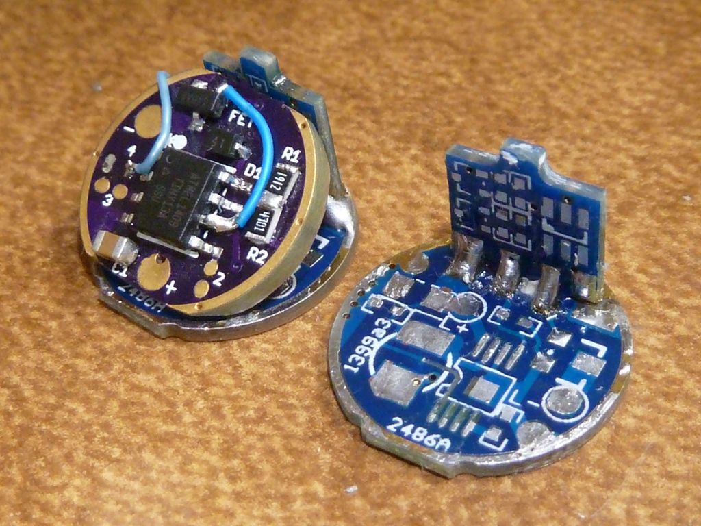
FWIW, here is the emitter setup… (this one is 3x royal blue 1x red, but I’ll be doing RGBA) I think I can probably put the driver directly onto the back of the pill, with only + and - wires going to the driver.

That emitter pill, the wires normally go out the bottom I assume, is there a reason those wires could not go directly to the driver (I think thats what you were saying?)

The pill appears to be about 20mm internally, I should be able to make up a 4 channel board in that space, the issue is how many 7135’s you would need, to fit 12 of them would be quite interesting.

That said I think it would be doable, just. All you would need is 4x banks of 3x 7135’s with the SOIC8 150mil pads + C1 + R5. The FET parts are not needed , if there is room I can try to fit C2 and the LVP could use the internal reference correct?

Plus pads for all the channels + power + e-switch + ground.

I should be able to fit 7x 7135’s on one side, possibly 8 if you can remove that lip at the bottom of the driver / sand it down for more clearance so I can put the 7135’s right on the edge of the driver.

The pill has no “internally” measurement. It’s solid except for the wire holes, and it doesn’t screw into its shell all the way. So, the driver can also be up to 25.4mm in diameter; no need to fit it inside a pill. The wires would ideally go directly from the driver to the emitters, with the solid heat sink between. Which means the driver will likely be held in place by its five short forward wires. To expose the MCU, it’ll need to be on the back side somewhere.

I’m assuming there will be no room for an e-switch unless we drop the voltage divider and voltage sense pin, and instead use the internal ref/VCC method which has been tossed around but never tried. No OTC either, for the same reason, unless it uses Mike C’s combined-pin method.

Pins:

  1. Reset (reserved)
  2. PWM2B
  3. PWM2A
  4. GND
  5. PWM1A
  6. PWM1B
  7. Voltage sense and/or e-switch and/or OTC
  8. VCC (and maybe voltage sense)

I’m hoping it won’t need an e-switch, but if so, that’s another pad or two on the back side of the driver. It’s weird having the switch between the battery and driver.

The driver will probably be pressed against the thinner switch section, which might make some of the layout awkward. Here’s the general idea:

The rear “button” there would actually be a charge port with its third pin unused, and the front button would need to be a clicky/latching switch. But an e-switch could go there instead, if I use all three charge port pins and connect a couple more wires to the driver.

Sorry this is getting so off-topic. This really has nothing to do with the TA driver any more.